


Part 1 of this article in the previous issue ended with the design brief for conductors in a speaker cable. I described why I chose a star-quad geometry using a 20-mil wire diameter in a 24-wire (12 bonded pairs) woven polarity. We continue with the next subheads under the Design Brief for speaker cables.
2) Dielectric materials
Again, Teflon® was chosen as it is the best solid dielectric there is. I needed a thin wall to bring the wires close together for inductance reduction, but capacitance is an issue with 24 closely spaced wires.
A capacitor is two parallel conductive plates with an insulator between them. To lower capacitance, I wanted a low-dielectric-constant plastic (Teflon®). To achieve the required low capacitance, more needs to be done to “thicken” the insulation without increasing loop area effects. This seems impossible to do, but it isn’t with the woven design described above. The final insulation wall was driven by balancing capacitive gains with inductive reduction. Dielectric geometry allowed this balance to be accomplished.
3) Dielectric geometry
The requirement to meet capacitance also drove the design to a weave pattern. Each polarity is separate; there is no interweaving of same polarity wires. What if we had wires with several AWG sizes? Current will flow along the path of least resistance. This does not mean current won’t flow in specific wires, just that the majority of the current magnitude is shifted to the easier path. Every wire will have current at all frequencies. The magnitude will change and follow Ohm’s law. Many differing wires sizes and electrical lengths can impact the signal arrival times across the audio band based on physical conductor lengths in composite wire-size designs.
If we take two wires with the same skin depth (same frequency point being considered), but one wire has twice the surface area, more current will flow into the larger surface area wire. It offers less resistance. But, the lower resistance wire is larger, and not ideal if we want the current across the wire to be more uniform. Bigger wires are better at lowering resistance at a given frequency because they have the most surface area. We use this at RF with a “skin” of copper to carry the lowest, yet still high, frequencies efficiently. The wire’s core under the copper is a material that is “filler” and has no current flow, such as steel or aluminum.
At lower frequencies the current is diffusion coupled evenly through the entire wire. So if you send just low frequencies, use as low a DCR wire as you can get.
Those are the extremes. Audio is weird in that we need to improve current coherence through the wire while it is trying to move to the outside surface. We don’t care about attenuation as much since it is negligible at audio frequencies. We make the conscious decision to go for forced current coherence with more small wires. This technically violates the practice of more “surface” area for lower attenuation at high frequencies for current coherence. Big wire offers more surface area for lower attenuation, while small wire offers better current coherence, but higher attenuation.
With interconnects, if you use one wire, the current delivery has to be considered to the load. RCA and XLR cables have near zero current flow into the high impedance load, so we can go for signal current coherence and suffer little attenuation. Speaker cables can’t use too few wires as there are 20-30 amps coursing through a speaker cable.
Good audio performance is about trying to time align the low and high frequencies, so the best and most consistent way to do this is to use more small wires that add up to the low frequency DCR needs, and are small enough to force the wire to see more and more cross sectional current usage at higher frequencies. This means several small insulated wires that all need to be the same “single” wire.
The unique woven design does a lot to reduce inductance and associated capacitance. How is 59% reduced inductance over a single bonded pair achieved?
A. ELECTROMAGNETIC FIELD CANCELLATION
- Star quad wire arrangement. Allows ideal geometry for low field strength
- Bonded-pair like polarity wires. Allows star quads to be formed throughout the weave
- Separate polarity fields are not parallel, to reduce field reinforcements. Fields between polarities have some cancellation since they cross at angles, and are not ever parallel. (Wires that cross at ninety degrees cancel completely)
B. CAPACITIVE REDUCTION
- Low dielectric constant plastic. Thinnest possible C-C with the lowest cap
- Woven pattern averages out the wire-to-wire distances significantly. Woven pattern separates the wires, and “tricks” the bulk capacitive value to be far lower
The last point on the capacitive reduction is also what we like in a flat design, but it is inconsistent. Average distance between any two wires in a braided polarity, and thus between polarities, is far more consistent. The weave moves all the wires evenly, and consistently, to a closest proximity position and a maximum proximity position throughout the weave. Capacitance and inductance do vary, but in a controlled and expected way. The fattened weave holds overall capacitance to an unexpectedly low value of 45 pF/foot in a cable with such high conductor count.
Low inductance leverages the same current direction in the bonded pairs, combined with the star-quad wire geometry periodicity. And finally, the tight textile weave between polarity halves, forces a low loop area, and with wires never being parallel, further reducing inductance.
The overall reactance of the cable is shown in the graph below:
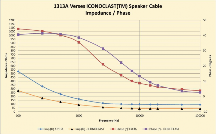
The chart illustrates a significant drop (yellow trace) in cable impedance compared to 1313A (blue trace). We know why this happened. The velocity, although variable, is nearly the same at each specific swept frequency point. We need to look at frequency-by-frequency calculations. The capacitance is linear across the entire audio band so that’s a set value.
We have a set value of capacitance, and a nearly set value of velocity (there will be slight variation) at a given frequency. What is changing is fundamentally the capacitance between cable designs for “impedance” characterization. The impedance equation is influenced by the change in capacitance, and thereby is the lower measured impedance, as the capacitance is in the denominator of the impedance equation. Increasing the capacitance from ~16 pF/foot to ~45 pF/foot decreases ICONOCLAST cable impedance. Speaker cables require low inductance, and need to get there without shooting capacitance through the roof.
Design is the overriding requirement, and materials, alongside unprovable theory, are second. Now we know why ICONOCLAST has the capacitance it does, as I can balance the inductance to industry-leading values, and still keep capacitance low, yet not so low as to increase impedance too much relative to the input requirement. Cables go up in impedance as you drop in frequency, the opposite of what we want. Listening tests have to decide if the superb inductance or impedance matching with much higher cable capacitance is ideal. Quick calculations will show capacitance problems with 8 ohm cables at audio once an amplifier is attached.
Don’t ignore the reactive time constants of L and C. We want an 8 ohm cable with no L and C, and zero resistance, and you can’t do that. Getting cable “impedance” reasonably low is more reliably safe for amplifiers.
4) Shield material and design considerations
I kept this topic here on purpose. Some may already know that the signal levels of low impedance cables negate the need for a shield. And that’s a good thing because a shield over a speaker cable is darn near always a bad thing for two reasons:
- A shield will always increase capacitance of the cable. The question is how much.
- To mitigate the capacitance increase, the shield must be moved significantly away from the core polarities, increasing the size of the cable.
Shields are only beneficial if the environment demands them. View a shield as a rain coat; great if you have water flying around but a major hindrance if you don’t. Coaxial cables are an exception as the shield defines the cable’s natural impedance. The ground-plane proximity and uniformity are vitally important with short-wavelength RF cables. Coaxial cables allow just that. Audio is not RF, and these shields are more FUD devices (Fear, Uncertainty, and Doubt) than than actually beneficial. This is especially in speaker cables whose signals are orders of magnitude over the background noise.
Audio seldom needs shielding on low-impedance cables and this is because magnetic fields decay rapidly with distance. The best defense is to move the low-frequency electromagnetic cables away from one another. The foil and even braid shields are higher frequency shields that are ineffective at much below 1 MHz. Magnetic fields lines need low permeability shield material (something a magnet will stick to) to route flux lines away from sensitive devices. A Faraday cage is a good example of a magnetic shield device. Low permeability metallic shields are a pain to use because they are stiff and heavy. Distance is the best remedy.
5) Jacket design and material considerations
All ICONOCLAST cables use FEP (fluorinated ethylene propylene) as the jacket to reduce UV-sensitivity and plasticizer migration, and provide chemical resistance. The cables are designed to last decades.
Summary
Little has been left to chance in the design of ICONOCLAST cables. All the products are born from strict measurements and the management of known electrical parameters. Belden’s philosophy is to make as low and R, L, and C cables as technically capable. The improvement to some may be unimportant. To others, and using different systems, they can be significant. The closer we manage the knowns, the better the tertiary elements will move along with those improvements.
All cables “react” differently. ICONOCLAST is designed to offer the most benign interaction possible between your amplifier and speaker by leveraging high-speed digital design principles to the much more complex audio band.
0 comments