In the previous article in this series, we discussed the design of an RCA interconnect, and how it’s important to have a good coaxial cable design in place before designing an XLR cable. Here, I lead you through the process that went into designing the Belden ICONOCLAST, but these are basic variables that every cable designer must work with. It may be worth repeating from the RCA article that distortions can’t be totally eliminated, so every cable is a compromise of some sort.
XLR Design Brief
1) Conductors
Both the copper conductor and size considerations were answered when we started the RCA cable. Though an XLR cable will mirror the reactive variables of inductance and capacitance, we don’t want to change the current coherence with a differing conductor diameter from the RCA design. But if we are to use the same wire between an RCA and XLR design, how to we work around the completely different geometry of each cable?
This is assuming you want to match the RCA and XLR properties and maintain the same signal quality, and we certainly do. A good RCA cable is designed first, and that used as a base for the XLR design.
2) Dielectric material
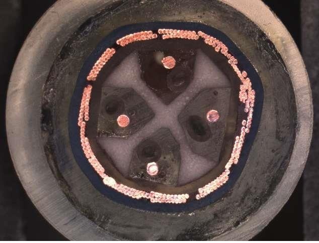
For our XLR cable, we will use four wires in a star quad configuration. This design uses two cross-connected wires for each polarity, which doubles-up the wire gauge for lower signal attenuation. Two 25 AWG wires have the direct current resistance of a single 22 AWG, yet have way better signal coherence.
I could have used a cheaper and easier two-wire XLR design but the inductive and signal coherence benefits of a star quad are too good to pass up, as we’ll see later. Star quads have a higher degree of CMRR (Common Mode Rejection Ratio) when properly signal balanced. Two wires of a star quad are a “positive” voltage, and two wires are a “negative” voltage (180 degrees out of phase), hence the term “balanced”. Some call this differential mode, since each signal is equal but different in polarity.

In the example above we show only two wires, but the concept is the same for a star quad design. The signal is encoded as +2 volts and -2 volts. The noise of +1 V in this example can’t “change its spots” relative to the cable’s twisted pairs, and shows up as the same voltage on each wire. The twist ratio helps make sure that the wires see the noise for the same amount of time, and this is vital to the function of the circuit.
Here is where balance is so important; the signal
ideally becomes the superposition of all the voltages, or +3 volts and -1 volt. No more, no less, and thus the signal voltages are still exactly 4 volts “apart” from each other: +2 to -2 with no noise, and +3 to -1 volts with 1 volt of noise.
The signals are fed into a difference amplifier that, you guessed it, looks at the “difference” between the two voltages and sees 4 volts with, or without, the noise. Ideally, the noise is absent at the difference amplifier’s output, and in order to do this, every wire has to be presented to the noise in the exact same way via cable twist, has to be the same length so the signal stays time-aligned down the wire. Also, every wire has to have the same attenuation. The difference amplifiers need to be nulled perfectly between gain halves. Believe it or not, this gets done really well with good quality products.
The control tolerance of the copper is 0.0005”, so attenuation issues are mitigated and CUB (Capacitance UnBalance) tests insure we see military-standard quality in the finished cable. All quality types of copper can be used in the XLR design; it is the overall cable structure that is the most “magic”, not so much the copper itself, although the copper draw process does influence the sound.
3) Dielectric geometry

This CAD drawing is what we have inside our XLR design so far, showing just two wires instead four. Remember I wanted to make inductance and capacitance reactive variables
exactly the same for each cable , RCA and XLR, with exactly the same wire size and draw science?
It’s a huge challenge to match capacitance between a single conductor coaxial cable, and a multi-conductor twisted cable. Capacitance is sensitive to the distance to a conductive plate area, all the way around a wire. In a coaxial cable this is easy: we put a ground around the wire at a known distance which stays the same for the entire run of the wire.
But in an XLR cable, we have shifting distances to the ground depending on the twist, and we have four wires all with their own capacitance. Somehow this is supposed to come out to around 12 pF/foot (with connectors), same as the RCA!
And now, inductance. Because of the many wires, the “loop area” of an XLR cable is huge, which means a very high inductance. It is a challenge to get a loop area as large as ~0.170” to produce an inductance as low as the 0.15 uH/foot needed to match the coaxial cable.
To get capacitance low enough, I use distance between the wires, air. This also has a direct effect on the inductance. By using air, I can set the center-to-center distance of the wires to meet my capacitance target, and because air is such a good dielectric, this distance is lower than is needed with most other materials. This lower distance means that inductance is also lower. How much air? Well,
exactly the same as the coaxial cables! How do we do that? Very carefully.
Let’s look at a section from the earlier CAD drawing showing the air chamber:

Each individual wire uses the same design from the RCA cable, so each wire’s loop area is the same across cables. The chamber, shown above has an area of 0.007552 sq in, and the area of my RCA air dielectric is 0.00754 sq in. Okay, it isn’t exact, but it’s off by only ~0.000009” sq in.
Careful measurements show that the capacitance and velocity of propogation of this design is very close to the coaxial cable. But what about inductance with that significantly larger loop area? Isn’t that going to kill this design? No, because of some properties of magnetic fields. Magnetic fields cancel if they see each other in opposite directions. If we can reduce magnetic field lines in the cable, we can directly reduce the measured inductance.
If you grasp a wire in your fist, with your thumb pointing in the direction of the current, your fingers around the wire point in the direction of the induced magnetic field. When you have four of these wires together, with two different voltage polarities (so that there are two different current directions), we see how these four circumferential fields cancel each other.

Where the arrows are pointing in opposite directions between any two wires (including ones across from each other on the diagonal), the field lines cancel. This allows larger wire-to-wire spacing in order to reduce capacitance, while also keeping inductance low. Now we know why I didn’t use a two-wire system! However, this inductive cancellation is less than what would be expected, because the field lines that extend around and outside the cable do the opposite of what is happening inside, and reinforce the magnetic field.
I finally tested both my RCA and XLR designs, and here are the results.

What we see above is impedance / phase for the XLR and RCA superimposed one on top the other. Note that there are four separate lines. We have two identical cables with exceptional reactive variables.
4) Shield material and design considerations
The outer shield is an important consideration in the design. A 95% BC (bare copper) braid is used. Audio cables are not RF designs, and the braid shield will
not shield low frequency magnetic interference. The common mode rejection ratio of the XLR is going to do that for us. The braid does knock down RFI by 80 dB, but this is a consideration only at high frequencies. The audio band of 20-20,000 Hz is a predominantly magnetic field frequency range where the B-fields decay at a ratio of 1/x^3. So distance is the best solution for isolation of cables with magnetic properties.
5) Jacket design and material considerations
All ICONOCLAST cables use Fluorinated Ethylene Propylene (FEP) as the jacket to reduce UV sensitivity, plasticizer migration, and provide chemical resistance. The cables are designed to last decades.
Summary
I hope that this design summary of ICONOCLAST RCA and XLR interconnect cables shows how important good design is for all your audio cables, and that every manufacturer has to manage the same variables to produce these results. There is little “magic” in the design of good cables. There are indeed tertiary variables that we can’t measure, but those should not excessively influence the ones we
can measure. Mother Nature abhors complexity, so the better managed the known variables in a cable, the better the cable may highlight “unknowns”. To put it another way, the more we put knowns into their proper place, the better we may distinguish the effects of the unknown. Wire draw science, for instance, can be heard better, and more fairly, in a superior electromagnetic design.
Belden has no special sauce or magic in its products, and I think the cables perform as well as they do because we did not design around “unknowns”, and then make it appear as though we had unique influence on those unknowns in the design.
Truly low R, L, and C cables are difficult to make when consideration is given to to manage all three variables in a balanced fashion. The designs can be simple looking, but frustratingly hard to manufacture, as processes are pushed to the limits of current capabilities. Belden’s focus is to make real measured values as low, and properly balanced, as we can.
Next: speaker cable design!


0 comments