


Previous installments discussed various design approaches to record lathe cutter heads, the history of Neumann and Scully lathes, and more.
As a general rule, records cut on Neumann lathes using Neumann cutter heads were cut with floating systems, whereas records cut on Scully lathes using Westrex cutter heads used an advance ball system with a manual setting of groove depth. Of course, Neumann lathes could also be used in manual mode, and they sometimes were, by certain engineers. For instance, since all pitch and depth automation systems require an “advance” or “preview” signal to operate (see my article in Issue 134 for further details on preview head tape machines and why these were required), it naturally follows that recording a performance direct-to-disk does not allow any of the automation systems to be used. All analog direct-to-disk recordings, therefore, are cut with both groove depth and pitch manually, set by an experienced engineer, regardless of the type of lathe and cutter head used. However, manually setting the depth on a floating head still results in phase shift and the “mechanical crossover” effect (see my article in Issue 163), while also giving up the advantage of automation.
It should also be noted that while manual pitch and depth settings often imply that these parameters are set prior to doing the cutting, and are kept constant throughout the cut, it did not necessarily have to be that way on any but the most early and primitive disk recording lathes, where pitch was either fixed, or changed by means of change wheels as in early screw-cutting lathes. In later disk recording lathes, pitch could be electronically variable but still set manually if desired, and the same held true for groove depth, although on advance ball systems, this parameter was mechanically rather than electronically variable. An experienced operator could therefore vary these parameters during the cut, to achieve the desired results. There was no rule book for that and no exact science to it. Manually varying the parameters mid-cut takes an incredible amount of skill, self-confidence and strong nerves. A wrong move can easily destroy a side or even cause expensive equipment damage. Some of the finest sounding records ever cut, however, were done exactly like that.
Technically, any cutter head could be either floated, or used with an advance ball system. There is nothing about a certain head that would make it impossible for it to be floated or used with an advance ball. Even the large and heavy Westrex cutter heads have been successfully floated, while on the other hand, many small and lightweight heads have been used with an advance ball.
A FloKaSon Caruso Stereophonic cutter head with a custom advance ball assembly added by the author. Courtesy of Agnew Analog Reference Instruments.
Typically, a cutter head that was designed to be used with an advance ball will have provisions for mounting and advance ball directly on the cutter head, or might even come with one by default; for example, the Westrex heads. In the case of Westrex, if the head was to be floated, the advance ball assembly could simply be removed. The European cutter heads of the stereophonic era (as opposed to the American-made Westrex heads) did not have any provisions for attaching an advance ball assembly, but this does not mean that it could not be done.
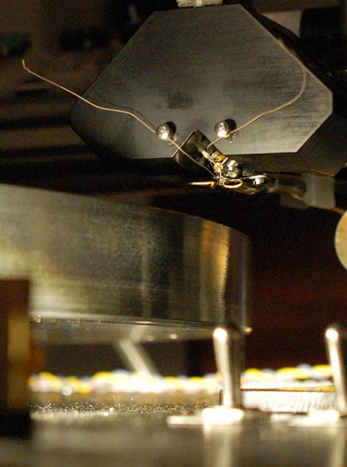
A FloKaSon Caruso cutter head with an advance ball assembly, chip suction tube and custom vacuum platter, retrofitted to a 19308 Fairchild lathe. Courtesy of Agnew Analog Reference Instruments.
As an example, I have successfully attached advance ball assemblies, that I designed and machined specifically for this application, to a couple of FLoKaSon Caruso heads (I think I can hear someone shouting “Nein, das ist verboten!” all the way from Switzerland). As the space for installing an advance ball assembly is limited, it was mounted behind the cutter head, rather than in front of it, a was customary with Westrex cutter heads. The knurled knob that controls the depth of cut on a FLoKaSon head is located on the side. The assembly utilized a concealed pushrod assembly and a precision- machined adjuster screw to move the advance ball arm. The design was inspired by the traditional layout used by most American V8 engines, which employed pushrods to actuate overhead valves (OHV), lifted by a single camshaft located directly above the crankshaft. These engines sound great, so why not apply the same principle to cut great-sounding records?
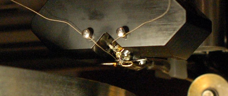
Top view of a heavily modified Fairchild lathe, fitted with a vacuum platter and an advance ball assembly on the FloKaSon Caruso cutter head, along with an oil dashpot on the suspension unit. The assembly right behind the cutter head, with the brass knurled knob off to the side, is the advance ball assembly. The knob is for setting the depth of cut. Courtesy of Agnew Analog Reference Instruments.
Essentially, the advance ball system and the floating system are merely the two different means of setting the depth of cut in a disk recording system. They both work, and both systems have been used to cut highly-regarded records. There are not that many options available for mechanically setting the depth of cut, on any type of cutting operation, where the end result is expected to deliver a surface finish in the low nanometer range (smaller than the wavelengths associated with visible light by quite a wide margin), in a single pass, with no subsequent finishing operations possible.
The principles of mechanical engineering associated with cutting records are in no way different to cutting operations in any other manufacturing sector. The traditional way of affixing a cutting tool to a machine tool for macro-machining (the machining of features over 0.040 inches or approximately 1 millimeter in size) is by rigidly holding it and feeding it into the work. Such operations usually consist of multiple passes prior to reaching the target dimension, and often require separate finishing operations. However, record grooves are only around 0.001 inches (.025 mm) deep, and due to the sound being recorded as the groove is being cut, the groove must be cut in a single pass.
This is micromachining territory.
The “floating tool” concept (the equivalent of a floating cutter head, in other machine tool applications) is not exclusive to record cutting, and neither is the advance ball arrangement. Both concepts have been used in other types of machine tools and measurement instruments where extreme accuracy was required.
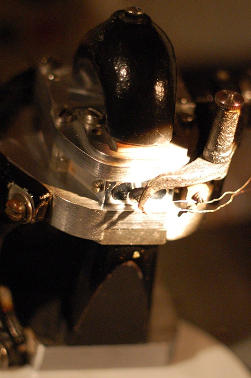
A Westrex 2B stereophonic cutter head with an advance ball assembly, viewed from below. Note the curved magnet pole pieces. Courtesy of Agnew Analog Reference Instruments.
As an example, ruling engines, remarkably accurate machines used for the manufacturing of diffraction gratings (as used in spectroscopy for applied physics research and metrology laboratories) have traditionally used a suspension unit, very similar to the ones used for cutting records, to float the grooving tool!
If the blank disks used in record cutting were totally flat, and the cutting lathe platter they are placed on would also be entirely flat, and there were no dynamic errors in the rotating system (which includes bearings, shafts, motors, the presence of structural vibrations, and so on), it might theoretically be possible to rigidly mount the cutter head, instead of suspending it or using an advance ball system, and feed the cutter head in to the blank record by means of a feedscrew, to set the depth of cut with great repeatability, while reading the depth of cut from a dial. However, blank records are very far from flat, platters do have surface errors, and the rotating system introduces a variety of dynamic motional errors, which the suspension is tasked with absorbing. It’s similar to how the suspension system in a car is meant to absorb bumps in the road and dynamic motional errors, to provide a smooth ride (with varying degrees of success, depending on the automobile manufacturer).
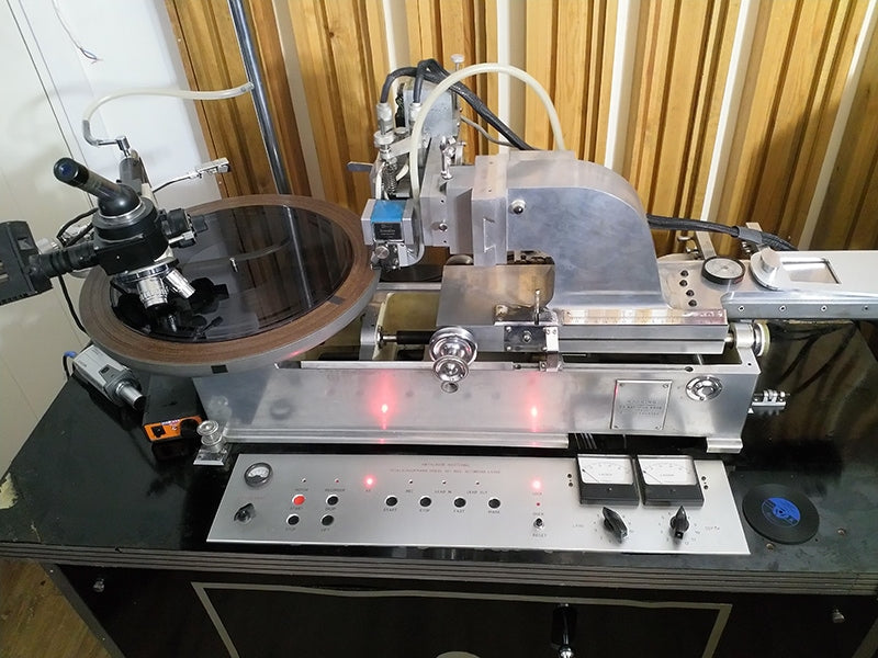
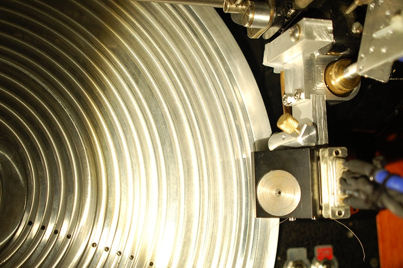
A Scully lathe with a Westrex 3D cutter head with an advance ball assembly. Courtesy of Jaakko Viitalähde, Virtalähde Mastering, Kuhmoinen, Finland.
In the next episode, we will investigate the effect of road bumps on the reception of vacuum tube car radios…no, we won’t, just kidding. I’ll spare you the details and get back to record cutting.
Header image: a heavily-modified Scully lathe, fitted with a vacuum platter and an A&M suspension unit, with a floated Westrex 3D cutter head. Photo courtesy of Eric Conn, Independent Mastering, Nashville, Tennessee.
Previous installments appeared in Issues 163, 162, 161, 160, 159, 158, 157, 156, 155, 154, 153, 152, and 151.
0 comments