Previous installments covered the earlier history of Neumann and Scully lathes.
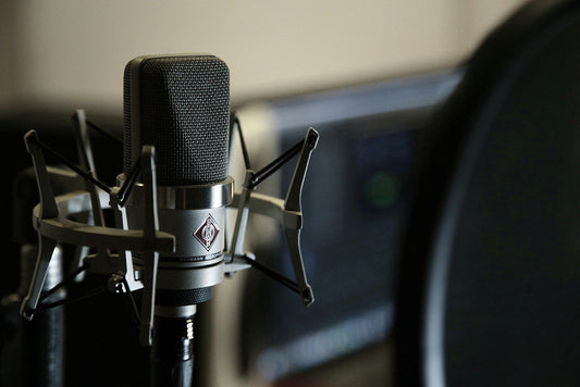
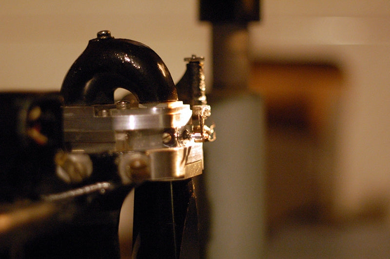
A Neumann SX-74 cutter head, with helium tub in the front. Courtesy of Greg Reierson, Rare Form Mastering, Minneapolis, Minnesota.
The Neumann SX-74 cutter head, introduced to accompany the company’s VMS-70 record cutting lathe, shared its external parts with the very similar Neumann SX-68. Both of these cutter heads were based on the long-established principle of motional feedback employed instead of mechanical damping, to create a transducer with a linear response across the audible spectrum. The earlier Teldec/Neumann ZS 90/45, SX-45, SX-15 cutter heads had also used motional feedback (but in a different configuration), as did their monophonic ES-59, and many competing products. The Westrex, HAECO, Ortofon and Fairchild stereophonic cutter heads, predating the SX-74, also all relied on motional feedback. So did a few monophonic cutter heads, apart from the aforementioned ES-59. The Westrex 2B used motional feedback, as well as some early Ortofon monophonic heads, but the originators of the idea were Leonard Vieth and Charles F. Wiebusch, who patented the concept for a vertical recording head in the 1930s. It was very similar in layout to one half of a Neumann SX-74 (or a Westrex 3D for that matter).
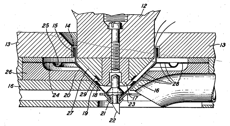
A drawing of the internal construction of Vieth and Wiebusch, from their patent, Vieth et. al Vibratory System, June 6, 1939.
For pretty much the entire stereophonic era, vinyl records were cut using motional feedback cutter heads. While the concept has been encountered in loudspeaker design, its implementation in cutter heads warrants some explanation. We can begin by looking at a plain-vanilla woofer design. We have a magnet system where the magnetic field is concentrated in a gap, and in this gap is placed the voice coil, consisting of wire wound around a former. At the end of this former, the speaker cone is attached. At the narrow end of that cone (in the middle of the driver) is what is called a spider, a flexible membrane that allows linear motion in and out, but limits lateral or rotary motion.
At the wide end of the cone is the surround, which again is designed to permit linear motion in and out, but to limit lateral or rotary motion.
The spider and surround form the suspension system of the loudspeaker driver, guiding it along the range of its excursion. The suspension system is what keeps the coil centered in the gap of the magnetic circuit and provides the restoring (mechanical) force for the coil to return to its rest position after traveling in or out. In a typical loudspeaker driver, the suspension components are made of rubber, fabric, or other resilient materials, that also provide damping.
Loudspeaker drivers, cutter heads, microphones and other similar transducers are resonant systems (as are many musical instruments). Their resonant frequency depends on the moving mass and the stiffness of the system. A resonant system will grossly accentuate the resonant frequency and will therefore not have a linear frequency response. Unless, that is, some means of damping is provided, to reduce the amplitude of the resonance and flatten the response of the system. In loudspeaker drivers, this damping is provided primarily by the suspension components.
Early monophonic cutter heads employed similar concepts, all of which broadly fall under the category of mechanical damping.

A selection of Presto monophonic cutter heads, employing mechanical damping, in the author’s lab, where repairs and modifications of such equipment frequently takes place. Courtesy of Agnew Analog Reference Instruments.
Cutter heads do not have spiders and surrounds, and they do not have cones either, as they don’t need to move air; they need to move a microscopic cutting stylus. Typically, early cutter heads would rely on pieces of rubber attached to the moving armature to provide damping. If the damping material deteriorated with age or became damaged, the system’s response would no longer be flat.
Motional feedback cutter heads, on the other hand, don’t require any damping materials. They did away with mechanical damping entirely and replaced it with electrical damping. Here, the coil suspension is essentially a spring, with no damping properties other than some unintentional friction. The open-loop response of the system (with the motional feedback disconnected) is very far from flat, with an extremely pronounced resonant frequency. A typical example of such a system consists of two coils: a drive coil that sets the system in motion, driven by a cutting amplifier, and a feedback coil, which produces a signal proportional to the velocity of the moving system. At the system’s resonant frequency, the velocity of the drive coil is much greater than at other frequencies, for the same amount of power to the drive coil. Conversely, the output of the feedback coil is also much greater. The feedback coil signal is inverted to be of opposite polarity to the signal going to the cutter head, and sent back to the cutting amplifier as negative feedback.
The Westrex 2B cutter head, one of the biggest, heaviest and best-sounding monophonic motional feedback cutter heads out there. Courtesy of Agnew Analog Reference Instruments.
The negative feedback signal essentially regulates the output of the cutting amplifier, reducing its output at resonance and increasing it at other frequencies. The closed-loop response of the system (with motional feedback applied) is therefore flat. However, this flattening is only effective within the range of accurate operation of the feedback coil. Outside this range, the response falls off rapidly. There are several factors conspiring to reduce the accuracy of such a system, so it is not a trivial task to ensure stable operation. Instability can be quite dramatic. In the case of the SX-74, it is normally used with the Neuman SAL-74 cutting amplifier, which is capable of putting out 1200 watts of peak momentary power, which would melt the coils in milliseconds at that power dissipation! Instability can be caused by phase shift between the signal to the drive coil and the signal generated by the feedback coil, as a result of a combination of electromechanical system parameters. If any instability occurs, it can cause the system to oscillate at full power, at a very high frequency, instantly destroying the cutter head and sometimes also the amplifier electronics! By the time the smoke becomes visible there is not much left of the coils, and nothing you can do about it other than sending the head off for repair. This type of repair on a Neumann SX-74 can easily cost upwards of $5,000, along with significant downtime.
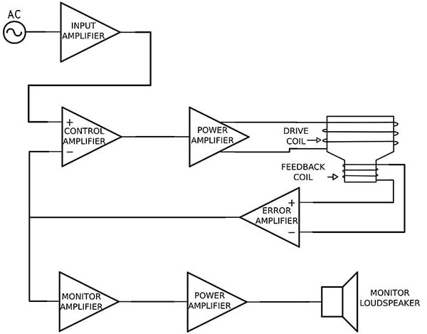
A block diagram of a motional feedback cutter head system, from “An Investigation of Motional Feedback Disk Recording System Design” by author J. I. Agnew, in the November 2018 issue of the Journal of the Audio Engineering Society.
The feedback loop is comprised of not only the cutter head, but also the cutting amplifier electronics, which consist of the drive amplifier, feedback amplifier, current and temperature measuring instrumentation, cutter head protection devices, and even the wiring. Excessive wiring capacitance, for instance, can also cause instability. As such, the electronics are very much part of the entire cutter head system, as evidenced by the fact that even as far back as the 1930s, the patents of Vieth and Wiebusch covered both the cutter head and the associated electronics all working together.
In the next episode, we will navigate our time capsule deeper into the coiled paths of cutter head territory!
Previous installments appeared in Issues 159, 158, 157, 156, 155, 154, 153, 152, and 151.
Header image: Neumann SX-74 cutter head on a Neumann VMS-70 lathe. Courtesy of Greg Reierson, Rare Form Mastering.