


Previous installments discussed various design approaches to record lathe cutter heads.
In terms of sound, floating record lathe cutter heads actually are at a disadvantage. The floating of the cutter head fulfills the conditions of a resonant mechanical system. The frequency of resonance is determined by the effective mass of the suspended head and the stiffness of the system. Above this frequency, everything works as expected. Below this frequency, however, the cutter head will just move up and down instead of recording the stylus motion as groove modulation. At the frequency of resonance, we have a crossover point. Does that sound somehow familiar? That’s because what happens at this crossover point is the exact equivalent to the crossover network in a loudspeaker. A loudspeaker crossover network uses electrical components to split the incoming signal into two or more separate frequency ranges, each being directed to a different driver (a woofer and a tweeter, in a typical 2-way system). The frequency at which the incoming signal is split is called the crossover frequency. (Multi-way loudspeakers will have more crossover points, but let’s keep to a 2-way system for our example.)
This is never a hard split, however. The woofer is still receiving signals above the crossover frequency, but progressively more attenuated, and the tweeter is still receiving signals below the crossover point in a similar manner. The rate of attenuation past the crossover point is defined by the slope of the filter, which is defined by its order (first-order, second-order, and so on). A first-order filter provides an attenuation of 6 dB/octave, a second-order filter 12 dB/octave, and so on. In the case of loudspeaker crossover networks, an electronic circuit is designed to intentionally split the audio range into narrower ranges, with the desired slopes, to best match the performance of the different drivers used in the system.
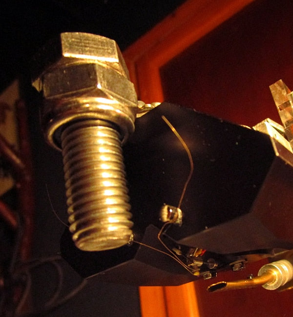
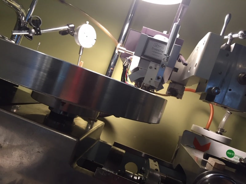
A FloKaSon Caruso cutter head, floated on a prototype suspension unit. The disproportionately large screw in the front is just adding additional mass to fine-tune the crossover frequency of the unintentional mechanical crossover filter which occurs in all floating head systems. Courtesy of Agnew Analog Reference Instruments.
A floating cutter head suspension system does the same thing, but “unintentionally,” if you will. The suspension system is, in effect, a mechanical crossover network, with a specific crossover frequency and a certain filter slope. Instead of utilizing resistors, capacitors and inductors, it is made up of the mechanical equivalents of these electrical components. The filter behavior of the suspension system can be analyzed using equivalent circuits. Above the crossover frequency, the audio is directed to the disk. Below the crossover point, however, it is simply lost to wasted motion. This is of course entirely unintentional, but it is an unavoidable side effect of floating a head.
If the crossover frequency of the mechanical system is around the lowest frequency of interest present in the recording, then no part of the frequency range will be left out. However, due to the filter slope and in accordance with filter theory, there will be a phase shift (a disturbance in the time domain) affecting frequencies that are well above the crossover point, into the audible range. In practice, on some lathe suspension unit and cutter head combinations, the crossover frequency can be as high as 50 Hz, limiting the low-frequency extension and time-domain accuracy of the system, even if the cutter head alone would have been capable of accurate performance down to 10 Hz. The transfer will be limited by the weakest link in the chain, as the entire complex electromechanical system is working all of the interactions of its individual components into the transfer function to the grooved medium. (The transfer function essentially describes what happens to the audio signal upon the transfer, in this case from an analog electrical signal to mechanical movement and storage within a groove).

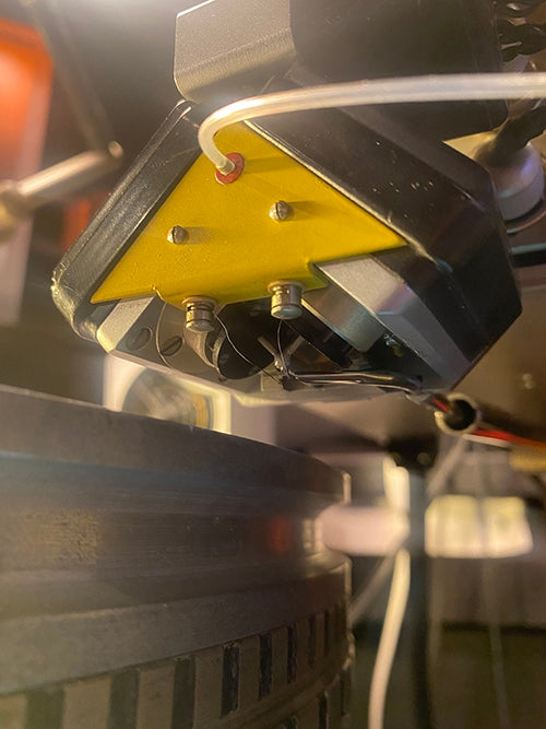
A Westrex 3D cutter head on a Scully lathe. This system is not floating, it is resting on an “advance ball.” The depth of cut is set by means of the large knurled knob on the front of the cutter head. Courtesy of Tor H. Degerstrøm at THD Vinyl Mastering, Oslo, Norway. Photo by Anja Elmine Basma.
The advance ball system (covered in Part 12, Issue 162), on the other hand, creates a rigid coupling between the cutter head and the disk. Instead of suspending the mass of the cutter head, it is meant to rest on a ball which rides on the surface of the record. The depth of cut is then defined as the relative height of the advance ball to the stylus tip. The cutter head is therefore essentially DC-coupled to the disk, in terms of its equivalent circuit. The frequency response at low frequencies on the disk is the same as the frequency response of the cutter head alone. There is no unintentional crossover filter and as such, there is no phase shift at low frequencies.
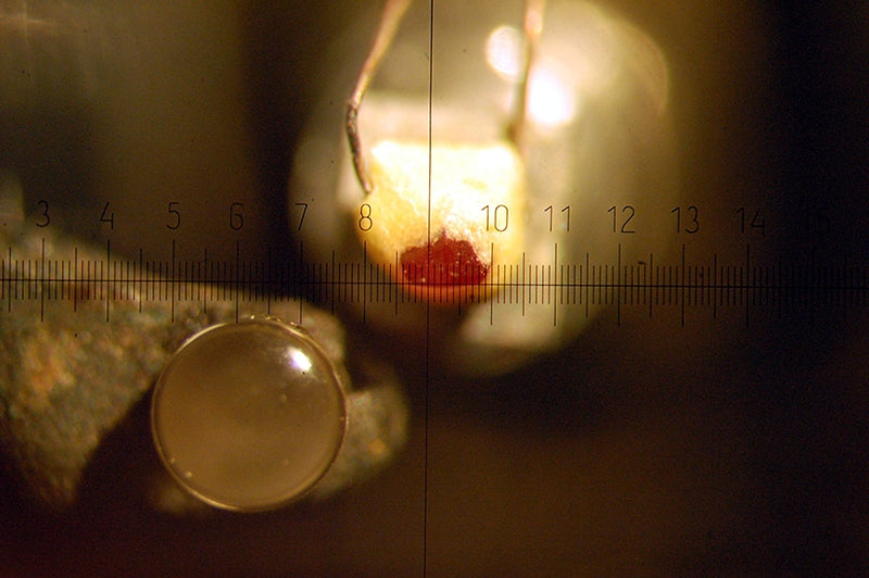
Microphotograph of the cutting stylus (red ruby) and advance ball (clear sapphire) on the underside of a Westrex 2B cutter head, repaired and modified by the author to accept a more obtainable type of cutting stylus. Courtesy of Agnew Analog Reference Instruments.
The unfortunate consequence of phase shift due to the presence of a mechanical crossover filter in floating head systems, is that the phase shift is in the same direction as the phase shift created by the mechanical crossover of the playback system, due to the floating of the playback cartridge, which is suspended by the tonearm. As discussed previously in Issue 97, the suspension of the playback cartridge also creates a mechanical crossover filter, the frequency of which depends upon the effective mass of the cartridge and the compliance of its own internal suspension (of the cantilever assembly that holds the playback stylus). Above this frequency, groove modulation causes the cantilever to move, generating an electrical audio signal. Below that frequency, the entire tonearm moves. At resonance, the tonearm is likely to move uncontrollably, due to the lack of damping, which causes skipping. Below resonance, any information contained within the groove structure is lost to unintentional tonearm motion, and no signal is generated.
The mechanism of the mechanical crossover on a playback system is exactly the same as the one encountered on a floating-head disk recording system. The phase shift of both is in the same direction, so it is accumulative, unlike the RIAA pre-emphasis and de-emphasis filters, where the phase shift caused by the de-emphasis network is the exact opposite of the phase shift caused by the pre-emphasis network, and they cancel out, delivering a signal free of the phase shifts that would normally be associated with such filter networks.
With mechanical crossovers, the phase shift of the floating head suspension just adds to the phase shift of the tonearm/cartridge system, resulting in more exaggerated overall phase shift. To make matters worse, most domestic loudspeakers exhibit pronounced phase shifts at low frequencies, contributing further to the problem.
In fact, many loudspeakers introduce phase shifts at low frequencies that are so much worse than those introduced by mechanical crossovers in disk recording and playback, that they even mask such effects incurred during the disk recording and playback process.
The floating cutter head suspension approach had an advantage in a different respect, an advantage that was widely utilized in disk recording systems and helped establish the floating systems in the industry.
A Neumann SX-74 cutter head, floated on a Neumann VMS-70 lathe. Courtesy of Greg Reierson, Rare Form Mastering, Minneapolis, Minnesota.
As automation systems began being introduced in disk recording, it was soon realized that an automatically-variable pitch system made it a lot easier for less-experienced operators to fit more music into a record side (as the parameters of recording pitch and groove depth are automatically adjusted by the machine in near real-time, in response to the audio signal, faster, more accurately and more repeatably than an inexperienced operator could hope for). In addition, the automation could be further increased by means of an automatically-variable groove depth system working together with the variable-pitch system. In a floating cutter head suspension, this was fairly easy to implement. An electromagnetic solenoid was placed in the suspension unit and the current through that solenoid could be varied to alter the groove depth, by creating forces that would pull the freely-suspended cutter head away from the record surface, or push it towards the record. Most Neumann lathes came with a combined automatically-variable pitch- and groove-depth system, and the ability to cut longer sides with less operator skill and perspiration was welcomed by the industry.
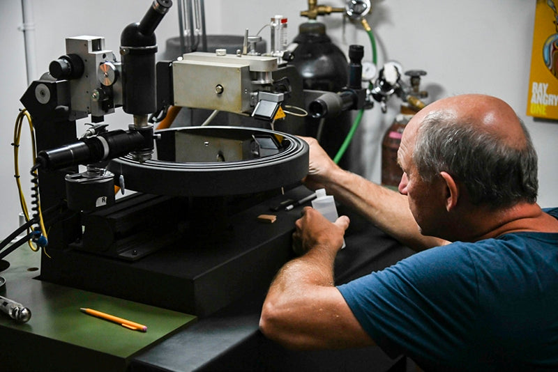
A Neumann SX-74 cutter head floated on a Neumann VMS-80 lathe, with Scott Hull fine-tuning the cutting parameters. Courtesy of Scott Hull, owner/chief engineer, Masterdisk, Peekskill, New York.
Implementing an automatically-variable groove depth system on a non-floating cutter head, where the groove depth is set by means of an advance ball, was far more complicated. One of the attempts at doing so, by Westrex, involved a servomotor assembly attached to the front of a Westrex cutter head, to directly act on the knob that was normally used to manually set the depth of cut. This looked rather intimidating, as the already massively big and heavy Westrex cutter head became almost twice as big and heavy. The other approach involved improving the point of the DC coupling between the cutter head and the disk. DC was injected into the cutter head drive coils, in addition to the audio signal. The DC would cause the coil to be displaced away from its normal resting point, thereby increasing or decreasing groove depth, since any displacement of the cutting stylus can only cut deeper into the blank disk, or shallower, depending on the direction. The basic depth would be set by the advance ball assembly and the cutter head was too heavy to go anywhere, even as the stylus would dig deeper into the lacquer disk, when displaced by direct current to the drive coils. This was a form of DC biasing of the drive coils.
Intentionally displacing a moving coil transducer from its center position was not without its side effects, however. There was a price to be paid in terms of the remaining available excursion, which led to increased distortion. As such, further efforts were directed towards simply removing the advance ball assembly from Westrex cutter heads and floating the heads using a suitable (or suitably modified) suspension unit. The phase shift from the mechanical crossover of the floating head was generally deemed less detrimental, comparedto what records would sound like if cut by less-skilled operators without automation systems to assist them. Despite the widespread availability and use of such automation systems, some of the world’s most widely respected mastering engineers, with decades of experience behind them, still prefer to use manual systems with no automation and/or advance ball cutter heads, for their work. There is certainly no consensus among cutting engineers on this point, and there is still room for diversity in this sector.
Westrex 3D cutter head floated on a Scully lathe, using the rare A&M suspension unit, with electronic groove depth control. Courtesy of Eric Conn, Independent Mastering, Nashville, Tennessee.
Header image: A FloKaSon Caruso cutter head, floated on the modified suspension unit of a pre-war Fairchild lathe, which was originally equipped with a Fairchild cutter head with an advance ball system. Courtesy of Agnew Analog Reference Instruments.
Previous installments appeared in Issues 162, 161, 160, 159, 158, 157, 156, 155, 154, 153, 152, and 151.
0 comments