Cutter heads for record-cutting lathes have come in various shapes and forms throughout the years, from the mechanically-damped moving-iron designs of the early monophonic era, to devices using oil and grease damping, to those employing magnetic feedback and motional feedback. (For an explanation of why cutter heads need to employ some kind of damping, see the previous installment in Issue 160.) Eventually, monophonic moving-iron cutter heads gave way to moving-coil configurations and eventually, stereophonic cutter heads.
Designing and constructing a good cutter head has always been a challenge. How many loudspeakers do you know that can accurately or even just “convincingly” cover the entire audible frequency range, using just a single full-range driver?
Well, a cutter head aims to accommodate the entire audible frequency range with a single transducer system, while keeping side effects such as distortion under control. To achieve that, the moving mass must be kept insanely low, but the transducer must also be powerful enough to accelerate that moving mass rapidly. It also needs to not self-destruct while doing so, for up to 30 minutes at a time (the longest record side that may be encountered, plus a bit of a safety margin). It is a bit like an endurance race. All parts must perform to their material limits, move fast, stop fast, stay on the desired path, and not overheat or break before the race is over.
In contrast to the automotive world, however, due to the nature of the disk recording and mastering work environment, it is neither practical nor desirable to take apart, rebuild and readjust the “vehicle” after every race, and you don’t get much of a chance for a pit stop either! The cutter head has to be able to not only survive, but also maintain its competitive performance over thousands of “races” over the course of years, with only an occasional stylus change as and when deemed necessary!


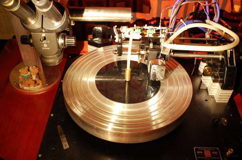
Header image and above images: An Audax R-56 moving-iron cutter head, rebuilt and modified by the author. This cutter head employs mechanical damping which tends to not age well, along with a multi-layer coil with very few turns of wire per layer, but a large number of layers.
In the early monophonic era of electrical recording, the “hot rods” of the time had a “single-cylinder engine” (a single transducer), with a rather heavy “piston” (a moving iron design with significant moving mass) and weren’t exactly tuned for high RPMs (with their crude coils, very basic magnetic circuits, mechanical damping that was sensitive to environmental conditions, and so on). The very basic cutter head models of the 1930s (RCA, Audax, early Fairchild, early Presto and others) had a frequency range of 50 Hz to 8 kHz, although some went as high as 10 kHz.
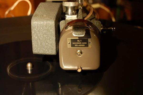
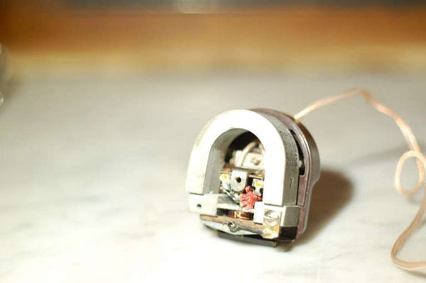
Above images: an RCA MI-4889 moving-iron monophonic cutter head. In some ways similar to the Audax seen earlier, this cutter head employs a stiff spring rod to keep the armature centered in the magnetic gap, with the pivot being held on a proprietary resilient material. An early and rather crude design, this one tends to not be as much affected by age. Here it’s in the process of being rebuilt by the author.
Nevertheless, impressive-sounding records have been cut with them, in the hands of crafty engineers who knew how to showcase the strengths of these earlier cutter heads while hiding their weaknesses!
The next generation of cutter heads were a bit more advanced, with improved magnetic circuits, improved coil geometry, improved damping configurations, and more accurate manufacturing techniques. These were capable of a frequency range of 30 Hz to 16 kHz with lower distortion and higher recording levels. Examples include the later Presto and Fairchild models, the Neumann MS-52H, and some of the simpler Grampian types.


Above images: the Neumann MS 52H represented the highest level of refinement in moving-iron cutter head design. It was well-made, and intended and advertised as suitable for 24/7 operation with no maintenance! It featured grease damping of the armature and a proprietary stylus mount, incompatible with anything else! This particular specimen was heavily modified by the author, giving it a conventional stylus mount and a feedback system. The precision-machined coil former can be seen on top of the head, prior to winding the new coil.
An important milestone in cutter head development was the Grampian/BBC moving-iron system with magnetic feedback. These cutter heads had a feedback coil wound right over the drive coil, on the same magnetic system, operating somewhat similar to a transformer. The feedback coil would pick up the magnetic irregularities caused by the motion of the iron armature (back-EMF), including resonances, response deficiencies and distortion products. These irregularities would be fed back to the cutting amplifier and “corrected” as part of a closed-loop servo control system.


Above images: the significantly more advanced Presto 1D cutter head, featuring a double-coil design with a so-called “balanced armature,” held by adjustable springs on a knife-edge bearing. The photo of the internal mechanism shows the author’s modifications, including custom-machined coil formers.
The high-frequency range left a lot to be desired, although the low frequencies were good, and the sensitivity was appalling (as a result of armature stiffness), but this system was a departure from established concepts of cutter head design, and was widely accepted by the market. It paved the way for further departures to be introduced. Among them was one of the most interesting cutting amplifiers ever made, designed specifically to be used with the Grampian head: The Gotham PFB-150.
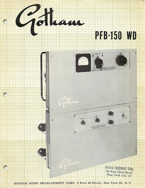
The Gotham PFB-150 vacuum tube cutting amplifier used triodes throughout, including the output stage, with power-driven 811A directly heated transmitting triodes.
This was a vacuum-tube beast, capable of delivering 150 watts to its load and weighing approximately 110 lbs. (a good watts-to-pounds ratio, as far as tube amps go). Very unusually for its time, it was a design using exclusively triode tubes, making it the only all-triode cutting amplifier in existence!
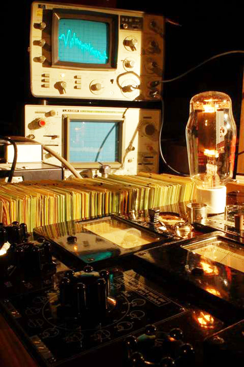
A directly-heated transmitting triode on the author’s tube testing bench: A Funke W20 tube tester, using a custom punch card for setting up the parameters, and a Hewlett-Packard 3580A spectrum analyzer displaying the noise spectrum of the tube with no audio signal applied. Yes, before getting carried away in the plastic fantastic era of computer printers, Hewlett-Packard had a long history of manufacturing fine laboratory instruments.
The output stage consisted of a pair of 811A directly-heated transmitting triodes, power-driven by a differential cathode follower made up by two 6BL7 double triodes, with the two halves of each tube paralleled!
Power drivers are few and far between in audio amplification. The term means that the driver stage is in itself a small power output stage. In the case of the PFB-150, the 6BL7 tubes provide the driving current into the grids of the 811A triodes, which are operated in the positive bias region (whereas most common audio amplifiers operate their output tubes with the grids well within the negative bias region, never to approach positive voltages with respect to the cathode). Traveling back a few episodes, to Issue 103, we shall remember that the heated cathode emits electrons (thermionic emission, after which my son, Thermion, was named), within the evacuated glass envelope of the tube. These electrons are negatively charged, and will be attracted by any electrode having a positive potential. The higher the positive potential (voltage), the higher the force of attraction. Most electrons will therefore be attracted to the anode (plate), which is operated at HT (high tension) voltage. If the grid(s) are allowed to assume a positive voltage with respect to the cathode, some of the electrons will be attracted to the grid(s) instead of the anode, either directly, or indirectly, after having bounced off the anode, or the glass envelope, or repelled by nearby electrons.
When electrons are attracted to the grid, due to the grid being at a positive potential, then the grid draws current, just like the anode does (although the grid current is lower, as much fewer electrons are attracted to the grid, compared to the plate). This is the interesting part. For the grid to be able to draw current, there must be a driver stage before it, capable of delivering current, just like the output stage does, when driving a load such as a loudspeaker or a cutter head. The driver stage would therefore need to be designed more like a power output stage, rather than a simple voltage amplifier, which is capable of delivering a large voltage swing, but practically no current. Most conventional audio amplifiers have an output stage operating in Class A1 or Class AB1, with the grids operated at negative potential with respect to the cathode, by means of negative bias (which is achieved either by means of cathode bias resistors, or through the use of a dedicated negative grid bias power supply, connected to the grids of the output tubes). Class A1 and AB1 output stages can be driven by voltage amplifiers as drivers. However, if we bias the grids of the output tubes to be positive, then we can no longer use a voltage amplifier to drive them. We need a driver stage that can deliver current during its voltage swing. In other words, it must deliver power, in watts.
In this configuration, the output stage is said to be working in Class A2 or AB2 configuration, the number 2 being used to denote that grid current is flowing. The number 1 in Class A1 and AB1 means that no grid current is permitted. The Gotham PFB-150 amplifier is designed so that grid current is always flowing in the output stage, even with no audio signal present. In the PFB-150, the parallel push-pull cathode follower stage formed by two 6BL7 tubes is DC-coupled to the grids of the 811A output triodes. The potential of the 811A grids (the bias of the output stage) is therefore set by the quiescent current of the 6BL7 tubes! The plate voltage of the 811A and 6BL7 tubes is around 550 volts DC, provided by a pair of 3B28 Xenon-filled rectifier tubes!
The entire amplifier, from input to output, is a true differential amplifier configuration (balanced), with no phase splitter or single-ended stages. This was quite a radical departure from all established notions of amplifier design for audio at the time, using configurations and tube types that were only encountered in radio broadcasting transmitters. In my opinion, this was one of the most fascinating cutting amplifiers ever made, and I have helped restore a few of them. Designed and marketed as a true laboratory amplifier, unfortunately, the Gotham PFB-150 was never very successful and there are very few of them surviving today.
Power-driven output stages attracted surprisingly little interest in the audio sector and with the exception of the PFB-150, they were largely ignored up until the mid 1990’s, when Eric Barbour (proprietor of Metasonix, https://www.metasonix.com/, a manufacturer of obscure vacuum tube synthesizers, and at the time employed as an applications engineer at Svetlana Electron Devices) published some of his vacuum tube amplifier designs, employing power-driven output stages, both in single-ended and push-pull configurations, in Vacuum Tube Valley (an influential but relatively short-lived publication, dedicated to the “history and quality of vacuum tube technology”). Since then, an extremely small group of inquisitive souls have revived the idea, experimenting with power driving a variety of tubes very rarely encountered in more “normal” audio circles. Very few commercial products have used this configuration in audio, although it wasn’t as “weird” in RF circuit design. One of the exceptions was the Magnetovolt Beyonder, a 200 Watt musical instrument amplifier designed by the author, featuring a unique circuit, transformer-coupled throughout, with a power-driven output stage and two 5U4G tube rectifiers in the power supply, with front panel EQ controls labeled “growl”, “quack” and “pling”.
By the time the PFB-150 was put on the market, triodes had pretty much fallen out vogue with amplifier designers, and all other cutting amplifiers of the tube era used pentodes or beam power tubes. The Westrex RA-1574 used the 7027, the early HAECO tube cutting amps used the 6550, the Neumann VG-1 used the EL156, and the Ortofon GO-541 used the EL34. There were also several simpler cutting amplifiers made by RCA, Presto, Rek-O-Kut and other manufacturers of disk recording lathes, primarily aimed towards the radio broadcasting industry rather than for vinyl record mastering and manufacturing, but these mostly followed the design trends and tubes of their time.
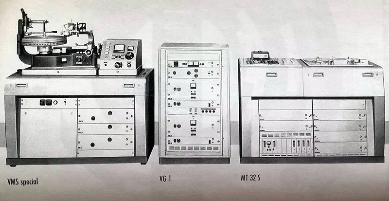
The Neumann VG1 vacuum tube cutting amplifier rack is in the middle of this brochure, with a Neumann disk mastering lathe on the left.
The other oddball cutting amplifier that clearly stands out among such devices was the Fairchild 641. It used 4CX250B ceramic tetrodes, driven by parallel push-pull 12BH7 cathode followers. The plate voltage on the 4CX250B was 1200 volts DC, and the amplifier utilized a 10 MHz RF positional feedback system, designed to work with the Fairchild 642 stereophonic cutter head introduced in the late 1950s and which contained something like a miniature radar within the cutter head, to detect the position of the moving system. The rest of the cutting amplifiers of the stereophonic era were more conventional in design and as the industry moved on to transistors, higher power was obtainable with much lower voltages and less-exotic devices.
In fact, the design differences between audio amplifiers and industrial welding equipment became increasingly smaller.
Some claim that welding equipment got better.
Others insist it just got lighter and easier to carry around when repairing farm equipment.
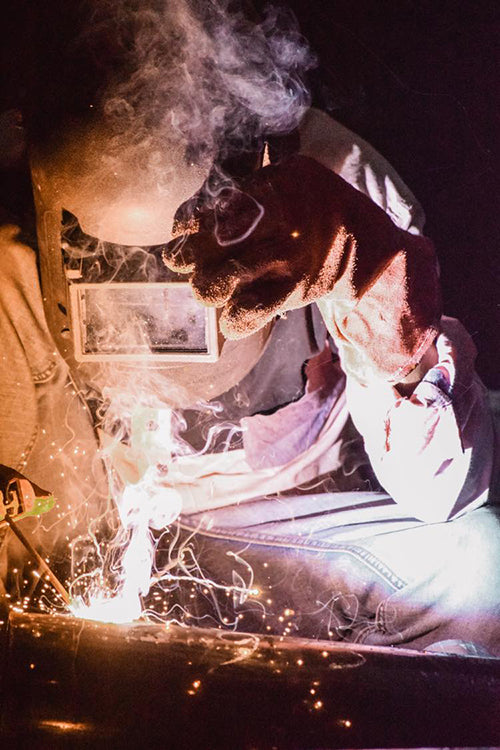
While most cutting engineers do not use their cutting amplifiers for welding, one little mistake can have a very similar effect upon the internal organs of the cutter head, as a result of pretty much the same operating principle: electrical current heats up the conductive metal, until it melts! Smells similar, with a bit of burned coil enamel for spicing. In the transistor era, audio amplifier circuits and welder circuits were no longer that much different from each other!
The Agnew Analog Reference Instrument Type 891 Cutting Amplifier falls under this category (if we would just forget about portability for a minute…). The circuit topology is not exactly groundbreaking (solid-state, DC-coupled totem pole configuration), but it was optimized as much as possible, with a minimalistic signal path, in an attempt to take it further away from welder territory and closer to good old-fashioned audio design. It can deliver enough current to weld with, if you’re in desperate need and don’t have a conventional welder, but with plenty of finesse to sound good when dealing with actual music. (Wire feeder and argon bottle available separately.)
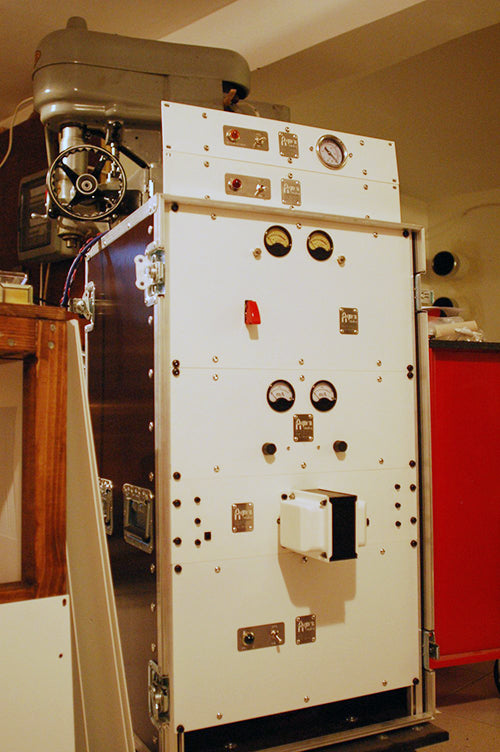
The Agnew Analog Reference Instruments Series 890 cutting amplifier rack, freshly assembled in the lab. From top to bottom, vacuum suction switchgear and vacuum gauge, stylus heat supply unit, input stage and incoming level metering for the audio signal, RIAA pre-emphasis stage, feedback amplifier and mixer, output current sensing and metering, cutter head protection unit, power amplification stage, and power supply unit. The lathe-control electronics are in a separate rack.
In the next episode, we shall examine the stereophonic era of cutter heads and the latest developments in the field.
Photos courtesy of Agnew Analog Reference Instruments.
Previous installments in this series appeared in Issues 160, 159, 158, 157, 156, 155, 154, 153, 152, and 151.