


Introduced in 1970, the Neumann VMS-70 was the result of the continued evolution of the company’s AM 31 (introduced in 1931 as the first Neumann disk recording lathe), keeping the same basic mechanical assembly throughout the entire half-century span, but introducing many new features in the control systems and audio electronics.
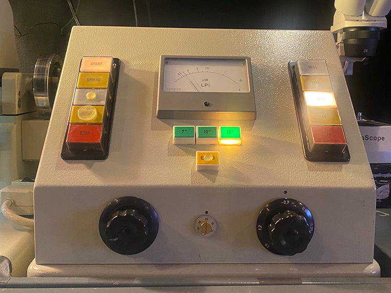
The pitch box of a Neumann VMS-70 lathe, with illuminated buttons and knobs controlling the cutting parameters. Courtesy of Greg Reierson of Rare Form Mastering in Minneapolis, Minnesota.
The lathe bed remained pretty much the same, although there were we three different versions. The early lathes had a slightly rounder overall shape and were made of aluminum. During the Second World War, there was a shortage of aluminum as a strategic war material, so a small run of lathe beds (around 30 pieces) was made of cast iron! This was considerably heavier and not as easy to machine as the aluminum beds. It is highly questionable if Neumann ever used these beds to build complete lathes, but some years ago, a number of them were discovered, in their as-cast, unmachined condition, in a warehouse in Germany (this discovery will be covered in greater depth in a future issue). There are reports of at least one lathe built up by Neumann during that time using one of the cast iron beds, but I have not yet been able to confirm this.
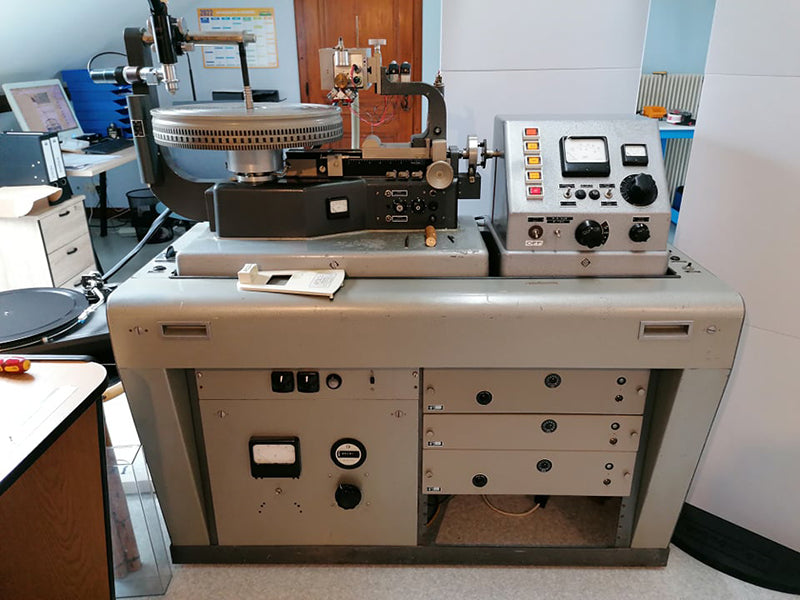
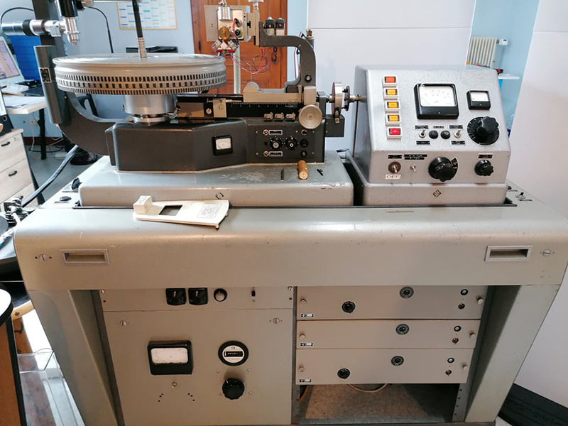
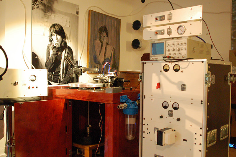
Neumann VMS special lathe, a complete system on a Neumann cabinet, filled with Neumann electronics. Courtesy of David Zanfrino of Cutting 70 in Corre, France.
The early Neumann lathes used this original bed style, in cast aluminum. At some point however (prior to the introduction of the VMS-66 in 1966), Neumann started using a slightly more squared up casting, for which a different pattern had been made. I wouldn’t call this a redesign, as all the parts that would bolt onto the earlier beds would still fit onto to the newer ones.
It could more appropriately be described as a face-lift, most probably prompted by the fact that by that point, the original patterns had been in use for over 30 years and were probably in need of replacement anyway. By the 1960s, Georg Neumann’s Mercedes-Benz was also a bit more squared up, compared to his earlier cars, so it was only natural that his lathe beds followed suit (Issue 155 contains a more in-depth analysis of Neumann lathe bed castings, for the profoundly nerdy reader).
The lathe bed of the Neumann VMS special. Nearly identical to the AM 32b, and similar to the VMS-66 and VMS-70, but with some big differences. Courtesy of David Zanfrino.
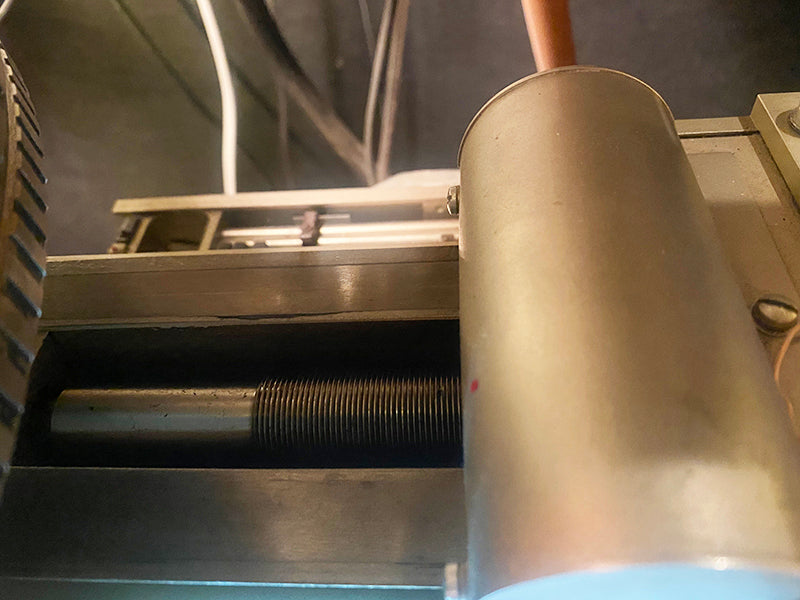
The bed itself was a very good design, which is why it lasted as long as it did, both in terms of years in production, but also in terms of their survival in the field. The later models needed increasingly more holes drilled into the hollow casting for additional switches, buttons, knobs and meters. The earlier lathes had a gear train which drove the leadscrew from the platter motor, and a hand crank for spirals (the usual separation between selections on a record, as well as the lead-out at the end). This was soon abandoned in favor of a separate leadscrew drive system consisting of two motors (one for recording pitch and one for spirals) and a mechanical differential, which would speed up the output shaft when the fast motor would be activated and slow it down again to the recording pitch of the slow motor as soon as the fast motor would stop. This way, two motors of different speeds could be coupled to the same output shaft, which could be made to automagically “obey” the appropriate motor as required. With the type of motor and control electronics used by Neumann at the time, it would have been difficult to achieve the extremely wide range of leadscrew speeds required for all three platter speeds (33-1/3, 45 and 78 rpm) and spirals for each, using a single motor, not to mention the requirement of having low noise. As such, it was decided to use two motors, for the higher and lower speeds. Mechanical speed reduction was used, and one of the two motors would transmit motion to a differential assembly by means of a drive belt (which needed to be reversed after a certain number of hours of use, and eventually replaced with a new one. Only one of the motors had a belt.)
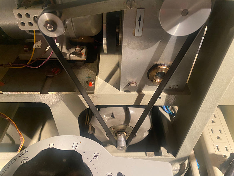
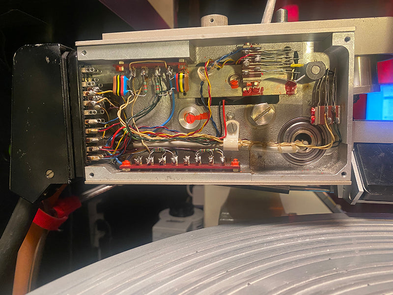
The differential leadscrew drive assembly, under the pitch-box of a Neumann VMS-70 lathe. Courtesy of Greg Reierson.
The horizontal slideway was a bit of an oddity in several ways. It was a dovetail slideway with a gib to adjust for wear, and was machined from steel. This steel piece was then bolted onto the cast aluminum bed, which was a strange idea as far as traditional machine tool engineering goes. The contact of steel and aluminum promotes dissimilar metal corrosion, and there would be inevitable geometric errors arising from such a mating.
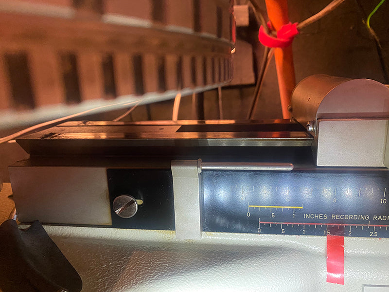
The dovetail slide on a Neumann VMS-70 with the platter visible on the top left. Courtesy of Greg Reierson.
To not make the lathe bed too long, the top part of the dovetail slide was kept short, but the load it had to carry (a fairly big and heavy suspension box with a cutter head weighing around 2 lbs.), was overhanging way too much, reaching over the platter. To balance that, and reduce excessive wear on the sliding surfaces and stick-slip behavior, a pair of ball bearings were added ahead of the top dovetail surface, acting as wheelie-bars of sorts and looking like a bit of an afterthought.
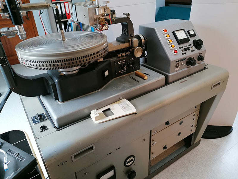
Neumann VMS special. Note that the controls on the lathe bed itself are different to the VMS-70. Courtesy of David Zanfrino.
With use over several years, uneven wear was a real issue, and the slideways had to either be replaced, or machined true again. In precision machine tool design, the slideway is traditionally machined directly on the lathe bed. However, with the Neumann lathe bed being made of aluminum, this would have resulted in excessive wear if a dovetail slide had been machined directly on the aluminum surface of the casting.
Bolt-on slideways have been used successfully in disk recording lathes, and even in some rare exceptions in the machine tool industry, notably the Hardinge HLV and related family of lathes, where a hardened steel dovetail slideway would be bolted onto a cast iron bed to ensure rigidity. In the case of the Hardinge HLV, the headstock, the carriage, tailstock and all other critical components of the machine all locate on the same long dovetail slide, which was finish-ground on the bed, thus ensuring geometric accuracy. The geometric reference point of the machine spindle was the same as that of the carriage and tailstock, so everything lined up (of course, precision manufacturing techniques are vital when such levels of accuracy are required).
A 1950s Hardinge HLV super-precision lathe, featuring dovetail bolt-on ways. Courtesy of Agnew Analog Reference Instruments.
On a Neumann lathe, the machine spindle and ways are independent of each other, which is not ideal for ultimate geometric accuracy, although this was compensated for by other means, which we shall be examining later.
Neumann VMS-70 leadscrew. The bulge on the right is the cover for the wheelie-bar bearings of the carriage. Courtesy of Greg Reierson.
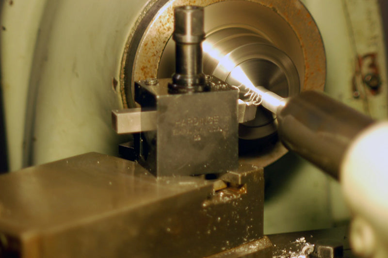
The leadscrew itself was also an oddity. It had a sawtooth thread form, which rendered it unidirectional. Unlike the vast majority of American disk recording lathes (which were used extensively in radio broadcasting and in the motion picture industry), Neumann lathes with a sawtooth-thread-form leadscrew could only cut outside-in records. A half-nut had to be disengaged to manually return the carriage back to the beginning. The half-nut itself was made of nylon, which had to be run without lubrication on the steel leadscrew. The Neumann manual warns against lubricating the leadscrew, which would cause rapid deterioration to the nylon half-nut. This was also a weak point, as the half-nut teeth could be easily stripped accidentally, when an operator would try to manually move the carriage but forget to first disengage the half-nut. This choice of materials was presumably used in an attempt to reduce any noise that could be produced by metal-to-metal contact. This was never an issue for several American lathes, and my 1930s Fairchild Aerial Camera Corporation lathe (described in detail in Bill Leebens’ article “Fairchild, Part 5” in Issue 89) demonstrated enviable performance using a stainless-steel leadscrew driving a half-nut with a phosphor bronze threaded insert. Not only was it dead quiet, but it also survived almost a century of heavy commercial service!
A heavily modified 1930s Fairchild disk mastering lathe, with an Agnew Analog Type 891-based high-fidelity cutting amplifier rack and pitch system. Courtesy of Agnew Analog Reference Instruments.
While the early Neumann suspension units were purely mechanical, the later models had a built-in “depth coil,” which would provide a means of electronic adjustment of the depth of cut. They also had head lift/drop solenoids, to electronically drop and lift the cutter head. A built-in oil dashpot could be seen as a characteristic bulge protruding right above the cutter head, which would provide damping of the vertical motion of the head during the cut.
The insides of a Neumann suspension unit on a VMS-70 lathe. Courtesy of Greg Reierson.
In Germany, one way to very quickly make yourself unpopular with your neighbors is to neglect the regular and precise trimming of your lawn, hedges and trees. Likewise, Neumann had a thing with grooming their cutter head wiring, so the audio wiring to the cutter head was routed to two DIN connectors close to the cutter head (they would never lower themselves to using anything invented in another country), from where the wiring could continue hidden within the suspension box, and out again through yet another DIN connector at the back, where it would not offend the neighbors…
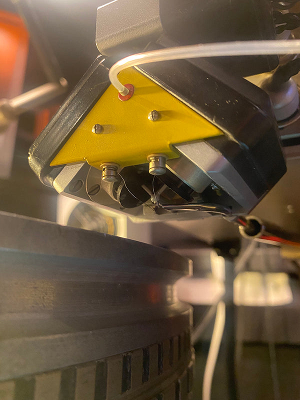
The oil dashpot and DIN audio connectors on a Neumann suspension box, with a Neumann SX-74 cutter head mounted. Courtesy of Greg Reierson.
Their head mounting system was also proprietary, which was by now becoming common practice in the disk recording industry. Fortunately, ample space around the suspension unit and adequate provision for adjustment made it easily possible to mount any cutter head one would wish to use, by means of adapters that could be custom-machined to match one proprietary mount to another. However, this went against the whole point of the Neumann system and philosophy: Thou shalt not connecteth a cutter head that does not sayeth Neumann on it, on thy Neumann lathe! Verstehst du?
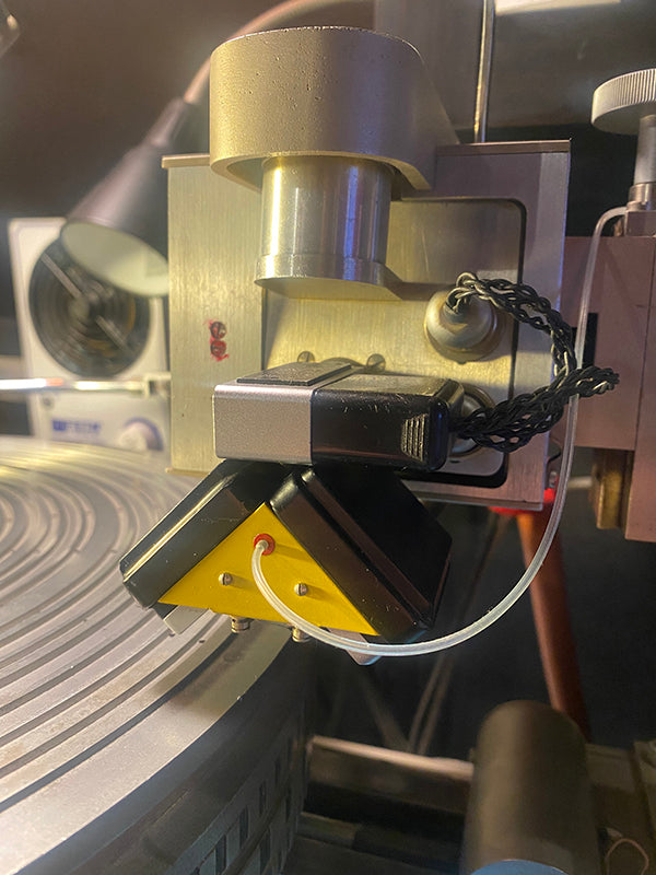
Neumann SX-74 stereophonic feedback cutter head on a Neumann VMS-70 lathe at Rare Form Mastering. Courtesy of Greg Reierson.
Previous installments appeared in Issues 157, 156, 155, 154, 153, 152, and 151.
Header image: Neumann VMS special, predating the VMS-66 and VMS-70, but with many similar features. Courtesy of David Zanfrino of Cutting 70.
0 comments