COPPER

A PS Audio Publication

Issue 199 • Free Online Magazine

Issue 199 Speaker Stories

Crossover Design Basics

Crossover Design Basics

Copper has an exchange program with FIDELITY magazine (and others), where we share articles, including this one, between publications.


A point source is the theoretical ideal; why, then, do almost all loudspeakers sport two, three or even more drivers spread out over a three-quarter meter baffle? Karl-Heinz Fink, mastermind and developer behind the products of FinkTeam, Epos and many other brands, sheds light on the basic principles and problems of crossover design for us.
 

Crossovers Explained


The human ear is an amazing organ: with the help of a single membrane, it is capable of capturing a frequency range from 20 to about 20,000 Hertz – that’s 10 octaves! Speaker drivers would break out in a sweat at the mere threat of such a challenge. That’s exactly why almost all developers spread the load across multiple drivers optimized for narrower bands. I write “almost all developers” because full-range [drivers] are a thing – and this approach has some merit, because as Karl-Heinz Fink explained to me at the very beginning of our conversation, “The best crossover is no crossover.” With this renunciation, however, you force some balancing acts upon yourself that are nigh impossible to master. If a driver is to cover the entire audible range, it can essentially neither be large enough nor small enough. Since diaphragms emit wavelengths smaller than their own diameter in a directional manner, small drivers are advantageous in the treble since they do not beam too much at high frequencies and thus enable a flat, even radiation pattern. However, as the frequency decreases, more air must be shoved around with each stroke, and diaphragm area is indispensable to do this.

In addition, a full-range driver cannot simply be left running unfiltered. The reason for this is the so-called “baffle step”: while wavelengths shorter than the width of the baffle are radiated forward by the speaker, longer waves (i.e. lower frequencies) “wrap” around the cabinet. In the low frequencies, therefore, twice as much air volume must be supplied with sound pressure than at the top. If a linear signal is fed to the loudspeaker over the entire bandwidth, the sound pressure is halved in this range, which corresponds to a drop in SPL of 6 decibels. The resulting “step” in the frequency response has to be smoothed out if a well-balanced loudspeaker is to emerge in the end. And speaking of cabinets: They, too, act as filters, just acoustically and not electrically. This becomes obvious at the speaker’s lower cutoff frequency: In combination with the driver, the cabinet forms a high-pass filter that causes the bass level in a closed system to drop below the cutoff frequency at 12 decibels per octave. In bass reflex speakers, the frequency is lower, but the drop below it is steeper at 24 decibels per octave. Midrange and tweeter drivers also exhibit such filtering functions in their respective enclosures. “When choosing a topology, it’s important to keep in mind that the acoustic and electrical effects added together determine the final result,” Fink explains.
 

Crossovers Explained


Frequency What?

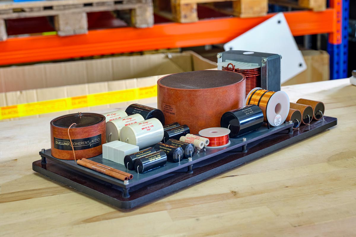
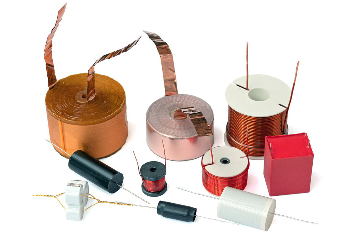
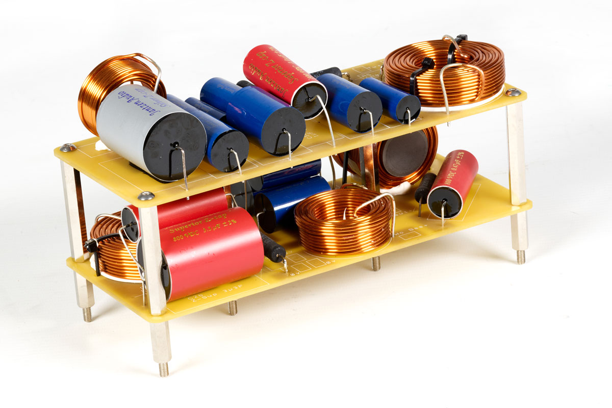
So in the end, there’s little getting around the necessary evil of a crossover – so how is it constructed? The essential components are high, low and bandpass filters, each implemented with a combination of capacitors and coils. In most crossovers, resistors are also built in, for example to adjust the level of the individual drivers to each other. A high-pass filter, i.e. a filter that allows only high frequencies to pass, consists in the simplest case of a capacitor that sits in series between the amplifier output and the tweeter. Its capacitance can be used to set the frequency below which the filter effect kicks in – the higher the capacitance, the lower the crossover frequency. The result is a “first order” filter. Such a filter lowers the signal level by 6 decibels per octave, i.e. with each halving of the frequency, the signal amplitude is halved. If you add an inductor to ground after the capacitor, you get a second-order high-pass filter that operates with twice the slope steepness: The amplitude decreases to a quarter with each octave, i.e. by 12 dB. By adding a second capacitor behind the coil, we get a third-order filter that separates at 18 dB/oct, and so on.

If we replace all the capacitors with coils in this setup, and vice versa, the high-pass filters become low-pass filters that operate according to the same laws: a single coil filters out high frequencies with a slope of 6 dB/oct. The decisive characteristic value in this context is called inductance, where larger values likewise lead to lower crossover frequencies. Analogous to the high-pass filter, an inductor and a capacitor result in a second-order low-pass filter (12 dB/octave), another inductor in a third-order filter, and so on.

Finally, the combination of the two aforementioned filters forms what we call a bandpass: a network that uses a low-set high-pass in conjunction with a high-set low-pass and allows the frequency band in between to pass, which then supplies signal to the midrange driver of a three-way loudspeaker, for example.

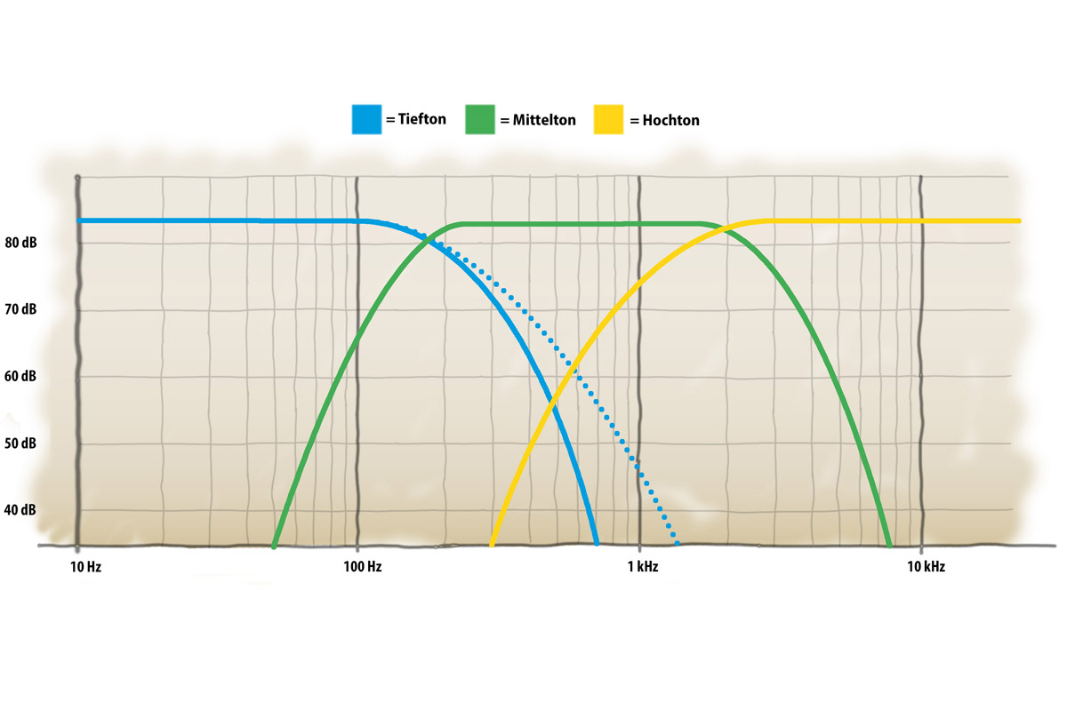
The above is what the transfer functions of the filters might look like in a typical three-way loudspeaker (with blue representing the bass, green the midrange, and yellow the treble). While the bandpass allocates a frequency band cut off at the top and bottom to the midrange, the woofer and tweeter are each bandwidth-limited on only one side by a lowpass and highpass, respectively. According to the electrical filter function, this hypothetical speaker would reproduce arbitrarily low frequencies, but the bass driver interacts with the cabinet to form an acoustic high-pass filter that imposes a lower cutoff frequency – about 30 - 40 Hz for a typical floorstanding speaker. The dotted line at the low pass filter represents a filter of the same cutoff frequency but of a lower order (e.g. 2nd instead of 3rd order; figure not to scale).

Another important parameter of the filter function is the damping – the so-called quality factor or Q-value, which describes how smoothly or abruptly the transfer function approaches its slope in the range of the crossover frequency. At low Q values, the transition occurs gradually over a wide frequency range; at higher Q values, it occurs correspondingly faster.

Thus, a crossover for a two-way loudspeaker consists of a high-pass filter in front of the tweeter and a low-pass filter in front of the mid-bass driver. Each of the two drivers takes care of the frequency range it handles best, and thus everything should be fine. Unfortunately, however, this is not the case: in fact, the filtering delays the signal by 90 degrees per filter order – so it’s not just a matter of achieving a smooth frequency response, but also of getting the phase behavior well enough under control to produce a predictable, even and time-correct dispersion pattern. In choosing the type of filter, one has “the choice between cholera and plague,” as Fink describes.

Smooth Frequency Response…
Crossovers Explained

The two most common filter types are Butterworth and Linkwitz-Riley filters, which differ not only in filter order but also in their quality factor: Linkwitz-Riley filters are even-order filters with a Q value of 0.5, which means that at the crossover frequency, both ways – mid/bass and treble – are attenuated by 6 dB each compared to the input level. Second-order Linkwitz-Riley filters produce a phase offset of 180 degrees, which would cause the frequency branches to cancel each other out. The solution is quite simple: simply reverse the polarity of one of the two drivers, causing the phase to rotate another 180 degrees and thus arrive back at zero – albeit delayed by one wavelength. With a fourth-order filter, this problem solves itself by a 360-degree phase rotation. The time delay is not a significant problem as long as the crossover frequency is reasonably high – at 2.5 kilohertz we’re talking 0.4 milliseconds.

Since the -6 dB at the crossover frequency correspond to half the original signal amplitude, our elementary school math skills tell us that the two branches add up exactly to the correct level – but that’s only true on-axis. If the listener moves his head up or down, the phase of the frequency branches shifts in relation to each other. They now no longer add up completely or, in extreme cases, even cancel each other out, causing the level to drop off-axis in the transition range. “Especially at low crossover frequencies – for example, with three-way loudspeakers – this can lead to a rather thin-sounding low end, since less power is radiated into the room overall as a result of the filtering,” Fink elaborates. This can be mitigated with higher filter orders. The steeper filter slopes limit the problem to a narrower frequency band, but this in turn means accepting a greater overall time offset, which can be considerable at low crossover frequencies.

…Or Uniform Dispersion?

Or you decide for a Butterworth filter. This is characterized by an odd order and a Q-value of 0.707. This higher Q-value (one speaks of lower damping) means that the level at the crossover frequency is only 3 dB below the input signal – so in itself one would expect a hump of 3 dB when adding the two branches. However, due to the phase offset by 90 degrees (first-order), the levels do not add up completely and a largely smooth frequency response in the crossover region is the result. Since the phase turns towards 0 or 180 degrees as you move your head vertically (depending on whether you move up or down), you end up with a mixture of peaks and troughs that add up to more or less the right amount of radiated power. However, you can probably already see where the problem lies: Off the listening axis, Butterworth filters sometimes behave quite unpredictably and unrefined because of their “skewed” phase behavior, which makes it difficult to achieve an overall balanced frequency response.

“No matter how you do it, you do it wrong,” the cynic may now lament – and indeed, every loudspeaker is ultimately a box of compromises. Perfection doesn’t exist anywhere, however, and when you take a seat in your chair tonight, fire up the system, and press play, you’ll have another opportunity to marvel at how well compromises can work when the developers behind them know what they’re doing.

Special thanks to Karl-Heinz Fink.

More from Issue 199

View All Articles in Issue 199

Search Copper Magazine

#234 A Life in High-End Audio: The Roy Hall Interview, Part One by Frank Doris Sep 07, 2026 #234 Jason Greenlaw Offers His Personal Perspective on Jazz Guitar in Vantage Point by Frank Doris Sep 07, 2026 #234 Transcendent Phoenix: Lucina Yue Brings the Ancient Konghou Into Modern Times by Frank Doris Sep 07, 2026 #234 We Must All Follow Our Bliss by B. Jan Montana Sep 07, 2026 #234 How to Play in a Rock Band, 27: Leveling Up by Frank Doris Sep 07, 2026 #234 Ross Valory: Traveling Into New Musical Territory With All of the Above by Ray Chelstowski Sep 07, 2026 #234 Singer/Songwriter John David Schrader: On the Need to Create by Joe Caplan Sep 07, 2026 #234 The People Who Make Audio Happen: More From T.H.E. Show SoCal 2026 by Harris Fogel Sep 07, 2026 #234 The Vinyl Beat Digs Into the Gadget Box by Rudy Radelic Sep 07, 2026 #234 The Rolling Stones: Foreign Tongues Spoken Loud by Wayne Robins Sep 07, 2026 #234 Musical Moments by Rich Isaacs Sep 07, 2026 #234 Rags for Solo Piano and a Dog: David Chesky's Ragtime Music for the Modern Age by Frankly Speaking Sep 07, 2026 #234 HIGH END 2026, Vienna: Here to Stay by Carsten Barnbeck Sep 07, 2026 #234 From The Audiophile’s Guide: The Two Main Types of Loudpeakers – Box and Panel by Paul McGowan Sep 07, 2026 #234 Letting it Slide by Frank Doris Sep 07, 2026 #234 PS Audio in the News by PS Audio Staff Sep 07, 2026 #234 Long Playing by Peter Xeni Sep 07, 2026 #234 La Mer by B. Jan Montana Sep 07, 2026 #233 A Report From The Total Hi-Fi Experience Show SoCal 2026 by B. Jan Montana Aug 03, 2026 #233 Bluegrass Meets Country, Folk, Jazz and More in All That We Carried by The Squid City Slingers by Frank Doris Aug 03, 2026 #233 Corey Glover and One Tribe Nation: A Variegated Musical Collective by Ray Chelstowski Aug 03, 2026 #233 Excursions with Clive: The Late Clive Davis, A Personal History by Wayne Robins Aug 03, 2026 #233 AI, Art, and Music: A Conversation With Synthography Art by Joe Caplan Aug 03, 2026 #233 New American Symphonies: A Rediscovered Gem and a Vital Contemporary Work by Frank Doris Aug 03, 2026 #233 The Vinyl Beat: Genesis, the Dave Clark Five, Antonio Carlos Jobim and More by Rudy Radelic Aug 03, 2026 #233 How to Play in a Rock Band, 26: When It's Time to Record Your Music by Frank Doris Aug 03, 2026 #233 More From T.H.E. Show 2026, and the People Who Made it Happen by Harris Fogel Aug 03, 2026 #233 Underappreciated Artists, Part Three: Icehouse by Rich Isaacs Aug 03, 2026 #233 The Surprisingly Rich and Varied Music of Somalia by Steve Kindig Aug 03, 2026 #233 A Remarkable Discographic Legacy: The LP Recordings of the Basel Symphony Orchestra by Stephan Haberthür Aug 03, 2026 #233 From The Audiophile’s Guide: The Importance of Loudspeakers by Paul McGowan Aug 03, 2026 #233 From Swimming Pool to New Listening Room: A Conversation with Norman Varney of AV RoomService by Gilles Laferrière Aug 03, 2026 #233 PS Audio in the News by PS Audio Staff Aug 03, 2026 #233 Audio Jewelry by Peter Xeni Aug 03, 2026 #233 Enrich Your Life by Frank Doris Aug 03, 2026 #233 The Searcher by James Schrimpf Aug 03, 2026 #232 What came first: Art or Music? A Conversation With Artist Jose Acosta by Joe Caplan Jul 06, 2026 #232 Blow By Blow: The Jeff Beck Story: An Insightful Book About a Guitar Icon by Ray Chelstowski Jul 06, 2026 #232 Creed Over Camaraderie? by B. Jan Montana Jul 06, 2026 #232 Chronicles of a Sound Pilgrim at the 2026 Montreal Audiofest by Hugues Morin Jul 06, 2026 #232 The Vinyl Beat: Summer Grooves by Rudy Radelic Jul 06, 2026 #232 Hibbing Hillbilly Dylan's Acoustic Rock by Wayne Robins Jul 06, 2026 #232 Quad Quads and Plasmatronics Tweeters: An Extraordinary System Comes to Life by Frank Doris Jul 06, 2026 #232 In Praise of Live Music, Once Again by Ted Shafran Jul 06, 2026 #232 Allnic Audio’s L-9000 Preamplifier: Design and Engineering Innovation by Howard Kneller Jul 06, 2026 #232 “Best Of” Lists and Rage Bait: Enough Already by Frank Doris Jul 06, 2026 #232 Quick Takes: Bud Shank, Paulo Almeida, Jakob Dreyer, Tim Eriksen and Peter Irvine by Frank Doris Jul 06, 2026

Crossover Design Basics

Crossover Design Basics

Copper has an exchange program with FIDELITY magazine (and others), where we share articles, including this one, between publications.


A point source is the theoretical ideal; why, then, do almost all loudspeakers sport two, three or even more drivers spread out over a three-quarter meter baffle? Karl-Heinz Fink, mastermind and developer behind the products of FinkTeam, Epos and many other brands, sheds light on the basic principles and problems of crossover design for us.


Crossovers Explained


The human ear is an amazing organ: with the help of a single membrane, it is capable of capturing a frequency range from 20 to about 20,000 Hertz – that’s 10 octaves! Speaker drivers would break out in a sweat at the mere threat of such a challenge. That’s exactly why almost all developers spread the load across multiple drivers optimized for narrower bands. I write “almost all developers” because full-range [drivers] are a thing – and this approach has some merit, because as Karl-Heinz Fink explained to me at the very beginning of our conversation, “The best crossover is no crossover.” With this renunciation, however, you force some balancing acts upon yourself that are nigh impossible to master. If a driver is to cover the entire audible range, it can essentially neither be large enough nor small enough. Since diaphragms emit wavelengths smaller than their own diameter in a directional manner, small drivers are advantageous in the treble since they do not beam too much at high frequencies and thus enable a flat, even radiation pattern. However, as the frequency decreases, more air must be shoved around with each stroke, and diaphragm area is indispensable to do this.

In addition, a full-range driver cannot simply be left running unfiltered. The reason for this is the so-called “baffle step”: while wavelengths shorter than the width of the baffle are radiated forward by the speaker, longer waves (i.e. lower frequencies) “wrap” around the cabinet. In the low frequencies, therefore, twice as much air volume must be supplied with sound pressure than at the top. If a linear signal is fed to the loudspeaker over the entire bandwidth, the sound pressure is halved in this range, which corresponds to a drop in SPL of 6 decibels. The resulting “step” in the frequency response has to be smoothed out if a well-balanced loudspeaker is to emerge in the end. And speaking of cabinets: They, too, act as filters, just acoustically and not electrically. This becomes obvious at the speaker’s lower cutoff frequency: In combination with the driver, the cabinet forms a high-pass filter that causes the bass level in a closed system to drop below the cutoff frequency at 12 decibels per octave. In bass reflex speakers, the frequency is lower, but the drop below it is steeper at 24 decibels per octave. Midrange and tweeter drivers also exhibit such filtering functions in their respective enclosures. “When choosing a topology, it’s important to keep in mind that the acoustic and electrical effects added together determine the final result,” Fink explains.


Crossovers Explained


Frequency What?

So in the end, there’s little getting around the necessary evil of a crossover – so how is it constructed? The essential components are high, low and bandpass filters, each implemented with a combination of capacitors and coils. In most crossovers, resistors are also built in, for example to adjust the level of the individual drivers to each other. A high-pass filter, i.e. a filter that allows only high frequencies to pass, consists in the simplest case of a capacitor that sits in series between the amplifier output and the tweeter. Its capacitance can be used to set the frequency below which the filter effect kicks in – the higher the capacitance, the lower the crossover frequency. The result is a “first order” filter. Such a filter lowers the signal level by 6 decibels per octave, i.e. with each halving of the frequency, the signal amplitude is halved. If you add an inductor to ground after the capacitor, you get a second-order high-pass filter that operates with twice the slope steepness: The amplitude decreases to a quarter with each octave, i.e. by 12 dB. By adding a second capacitor behind the coil, we get a third-order filter that separates at 18 dB/oct, and so on.

If we replace all the capacitors with coils in this setup, and vice versa, the high-pass filters become low-pass filters that operate according to the same laws: a single coil filters out high frequencies with a slope of 6 dB/oct. The decisive characteristic value in this context is called inductance, where larger values likewise lead to lower crossover frequencies. Analogous to the high-pass filter, an inductor and a capacitor result in a second-order low-pass filter (12 dB/octave), another inductor in a third-order filter, and so on.

Finally, the combination of the two aforementioned filters forms what we call a bandpass: a network that uses a low-set high-pass in conjunction with a high-set low-pass and allows the frequency band in between to pass, which then supplies signal to the midrange driver of a three-way loudspeaker, for example.

The above is what the transfer functions of the filters might look like in a typical three-way loudspeaker (with blue representing the bass, green the midrange, and yellow the treble). While the bandpass allocates a frequency band cut off at the top and bottom to the midrange, the woofer and tweeter are each bandwidth-limited on only one side by a lowpass and highpass, respectively. According to the electrical filter function, this hypothetical speaker would reproduce arbitrarily low frequencies, but the bass driver interacts with the cabinet to form an acoustic high-pass filter that imposes a lower cutoff frequency – about 30 - 40 Hz for a typical floorstanding speaker. The dotted line at the low pass filter represents a filter of the same cutoff frequency but of a lower order (e.g. 2nd instead of 3rd order; figure not to scale).

Another important parameter of the filter function is the damping – the so-called quality factor or Q-value, which describes how smoothly or abruptly the transfer function approaches its slope in the range of the crossover frequency. At low Q values, the transition occurs gradually over a wide frequency range; at higher Q values, it occurs correspondingly faster.

Thus, a crossover for a two-way loudspeaker consists of a high-pass filter in front of the tweeter and a low-pass filter in front of the mid-bass driver. Each of the two drivers takes care of the frequency range it handles best, and thus everything should be fine. Unfortunately, however, this is not the case: in fact, the filtering delays the signal by 90 degrees per filter order – so it’s not just a matter of achieving a smooth frequency response, but also of getting the phase behavior well enough under control to produce a predictable, even and time-correct dispersion pattern. In choosing the type of filter, one has “the choice between cholera and plague,” as Fink describes.

Smooth Frequency Response…

Crossovers Explained

The two most common filter types are Butterworth and Linkwitz-Riley filters, which differ not only in filter order but also in their quality factor: Linkwitz-Riley filters are even-order filters with a Q value of 0.5, which means that at the crossover frequency, both ways – mid/bass and treble – are attenuated by 6 dB each compared to the input level. Second-order Linkwitz-Riley filters produce a phase offset of 180 degrees, which would cause the frequency branches to cancel each other out. The solution is quite simple: simply reverse the polarity of one of the two drivers, causing the phase to rotate another 180 degrees and thus arrive back at zero – albeit delayed by one wavelength. With a fourth-order filter, this problem solves itself by a 360-degree phase rotation. The time delay is not a significant problem as long as the crossover frequency is reasonably high – at 2.5 kilohertz we’re talking 0.4 milliseconds.

Since the -6 dB at the crossover frequency correspond to half the original signal amplitude, our elementary school math skills tell us that the two branches add up exactly to the correct level – but that’s only true on-axis. If the listener moves his head up or down, the phase of the frequency branches shifts in relation to each other. They now no longer add up completely or, in extreme cases, even cancel each other out, causing the level to drop off-axis in the transition range. “Especially at low crossover frequencies – for example, with three-way loudspeakers – this can lead to a rather thin-sounding low end, since less power is radiated into the room overall as a result of the filtering,” Fink elaborates. This can be mitigated with higher filter orders. The steeper filter slopes limit the problem to a narrower frequency band, but this in turn means accepting a greater overall time offset, which can be considerable at low crossover frequencies.

…Or Uniform Dispersion?

Or you decide for a Butterworth filter. This is characterized by an odd order and a Q-value of 0.707. This higher Q-value (one speaks of lower damping) means that the level at the crossover frequency is only 3 dB below the input signal – so in itself one would expect a hump of 3 dB when adding the two branches. However, due to the phase offset by 90 degrees (first-order), the levels do not add up completely and a largely smooth frequency response in the crossover region is the result. Since the phase turns towards 0 or 180 degrees as you move your head vertically (depending on whether you move up or down), you end up with a mixture of peaks and troughs that add up to more or less the right amount of radiated power. However, you can probably already see where the problem lies: Off the listening axis, Butterworth filters sometimes behave quite unpredictably and unrefined because of their “skewed” phase behavior, which makes it difficult to achieve an overall balanced frequency response.

“No matter how you do it, you do it wrong,” the cynic may now lament – and indeed, every loudspeaker is ultimately a box of compromises. Perfection doesn’t exist anywhere, however, and when you take a seat in your chair tonight, fire up the system, and press play, you’ll have another opportunity to marvel at how well compromises can work when the developers behind them know what they’re doing.

Special thanks to Karl-Heinz Fink.
0 comments

Leave a comment

0 Comments

Your avatar

Loading comments...

🗑️ Delete Comment

Enter moderator password to delete this comment:

✏️ Edit Comment

Enter your email to verify ownership: