COPPER

A PS Audio Publication

Issue 54 • Free Online Magazine

Issue 54 FEATURED

Cables: XLR Interconnect Design

In the previous article in this series, we discussed the design of an RCA interconnect, and how it’s important to have a good coaxial cable design in place before designing an XLR cable. Here, I lead you through the process that went into designing the Belden ICONOCLAST, but these are basic variables that every cable designer must work with. It may be worth repeating from the RCA article that distortions can’t be totally eliminated, so every cable is a compromise of some sort.

XLR Design Brief

1) Conductors

Both the copper conductor and size considerations were answered when we started the RCA cable. Though an XLR cable will mirror the reactive variables of inductance and capacitance, we don’t want to change the current coherence with a differing conductor diameter from the RCA design. But if we are to use the same wire between an RCA and XLR design, how to we work around the completely different geometry of each cable? This is assuming you want to match the RCA and XLR properties and maintain the same signal quality, and we certainly do. A good RCA cable is designed first, and that used as a base for the XLR design.

2) Dielectric material

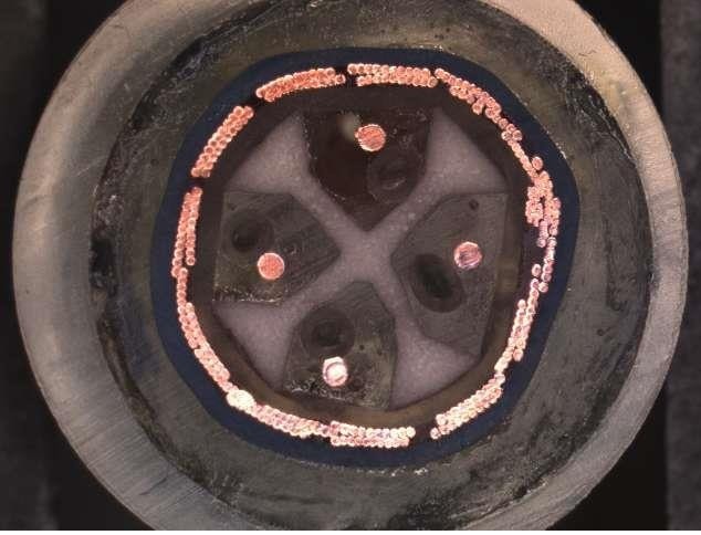
For our XLR cable, we will use four wires in a star quad configuration. This design uses two cross-connected wires for each polarity, which doubles-up the wire gauge for lower signal attenuation. Two 25 AWG wires have the direct current resistance of a single 22 AWG, yet have way better signal coherence. I could have used a cheaper and easier two-wire XLR design but the inductive and signal coherence benefits of a star quad are too good to pass up, as we’ll see later. Star quads have a higher degree of CMRR (Common Mode Rejection Ratio) when properly signal balanced. Two wires of a star quad are a “positive” voltage, and two wires are a “negative” voltage (180 degrees out of phase), hence the term “balanced”. Some call this differential mode, since each signal is equal but different in polarity. In the example above we show only two wires, but the concept is the same for a star quad design. The signal is encoded as +2 volts and -2 volts. The noise of +1 V in this example can’t “change its spots” relative to the cable’s twisted pairs, and shows up as the same voltage on each wire. The twist ratio helps make sure that the wires see the noise for the same amount of time, and this is vital to the function of the circuit. Here is where balance is so important; the signal ideally becomes the superposition of all the voltages, or +3 volts and -1 volt. No more, no less, and thus the signal voltages are still exactly 4 volts “apart” from each other: +2 to -2 with no noise, and +3 to -1 volts with 1 volt of noise. The signals are fed into a difference amplifier that, you guessed it, looks at the “difference” between the two voltages and sees 4 volts with, or without, the noise. Ideally, the noise is absent at the difference amplifier’s output, and in order to do this, every wire has to be presented to the noise in the exact same way via cable twist, has to be the same length so the signal stays time-aligned down the wire. Also, every wire has to have the same attenuation. The difference amplifiers need to be nulled perfectly between gain halves. Believe it or not, this gets done really well with good quality products. The control tolerance of the copper is 0.0005”, so attenuation issues are mitigated and CUB (Capacitance UnBalance) tests insure we see military-standard quality in the finished cable. All quality types of copper can be used in the XLR design; it is the overall cable structure that is the most “magic”, not so much the copper itself, although the copper draw process does influence the sound.
3) Dielectric geometry

This CAD drawing is what we have inside our XLR design so far, showing just two wires instead four. Remember I wanted to make inductance and capacitance reactive variables exactly the same for each cable , RCA and XLR, with exactly the same wire size and draw science? It’s a huge challenge to match capacitance between a single conductor coaxial cable, and a multi-conductor twisted cable. Capacitance is sensitive to the distance to a conductive plate area, all the way around a wire. In a coaxial cable this is easy: we put a ground around the wire at a known distance which stays the same for the entire run of the wire. But in an XLR cable, we have shifting distances to the ground depending on the twist, and we have four wires all with their own capacitance. Somehow this is supposed to come out to around 12 pF/foot (with connectors), same as the RCA! And now, inductance. Because of the many wires, the “loop area” of an XLR cable is huge, which means a very high inductance. It is a challenge to get a loop area as large as ~0.170” to produce an inductance as low as the 0.15 uH/foot needed to match the coaxial cable. To get capacitance low enough, I use distance between the wires, air. This also has a direct effect on the inductance. By using air, I can set the center-to-center distance of the wires to meet my capacitance target, and because air is such a good dielectric, this distance is lower than is needed with most other materials. This lower distance means that inductance is also lower. How much air? Well, exactly the same as the coaxial cables! How do we do that? Very carefully. Let’s look at a section from the earlier CAD drawing showing the air chamber: Each individual wire uses the same design from the RCA cable, so each wire’s loop area is the same across cables. The chamber, shown above has an area of 0.007552 sq in, and the area of my RCA air dielectric is 0.00754 sq in. Okay, it isn’t exact, but it’s off by only ~0.000009” sq in. Careful measurements show that the capacitance and velocity of propogation of this design is very close to the coaxial cable. But what about inductance with that significantly larger loop area? Isn’t that going to kill this design? No, because of some properties of magnetic fields. Magnetic fields cancel if they see each other in opposite directions. If we can reduce magnetic field lines in the cable, we can directly reduce the measured inductance. If you grasp a wire in your fist, with your thumb pointing in the direction of the current, your fingers around the wire point in the direction of the induced magnetic field. When you have four of these wires together, with two different voltage polarities (so that there are two different current directions), we see how these four circumferential fields cancel each other. Where the arrows are pointing in opposite directions between any two wires (including ones across from each other on the diagonal), the field lines cancel. This allows larger wire-to-wire spacing in order to reduce capacitance, while also keeping inductance low. Now we know why I didn’t use a two-wire system! However, this inductive cancellation is less than what would be expected, because the field lines that extend around and outside the cable do the opposite of what is happening inside, and reinforce the magnetic field. I finally tested both my RCA and XLR designs, and here are the results. What we see above is impedance / phase for the XLR and RCA superimposed one on top the other. Note that there are four separate lines. We have two identical cables with exceptional reactive variables.

4) Shield material and design considerations

The outer shield is an important consideration in the design. A 95% BC (bare copper) braid is used. Audio cables are not RF designs, and the braid shield will not shield low frequency magnetic interference. The common mode rejection ratio of the XLR is going to do that for us. The braid does knock down RFI by 80 dB, but this is a consideration only at high frequencies. The audio band of 20-20,000 Hz is a predominantly magnetic field frequency range where the B-fields decay at a ratio of 1/x^3. So distance is the best solution for isolation of cables with magnetic properties.

5) Jacket design and material considerations

All ICONOCLAST cables use Fluorinated Ethylene Propylene (FEP) as the jacket to reduce UV sensitivity, plasticizer migration, and provide chemical resistance. The cables are designed to last decades.

Summary

I hope that this design summary of ICONOCLAST RCA and XLR interconnect cables shows how important good design is for all your audio cables, and that every manufacturer has to manage the same variables to produce these results. There is little “magic” in the design of good cables. There are indeed tertiary variables that we can’t measure, but those should not excessively influence the ones we can measure. Mother Nature abhors complexity, so the better managed the known variables in a cable, the better the cable may highlight “unknowns”. To put it another way, the more we put knowns into their proper place, the better we may distinguish the effects of the unknown. Wire draw science, for instance, can be heard better, and more fairly, in a superior electromagnetic design. Belden has no special sauce or magic in its products, and I think the cables perform as well as they do because we did not design around “unknowns”, and then make it appear as though we had unique influence on those unknowns in the design. Truly low R, L, and C cables are difficult to make when consideration is given to to manage all three variables in a balanced fashion. The designs can be simple looking, but frustratingly hard to manufacture, as processes are pushed to the limits of current capabilities. Belden’s focus is to make real measured values as low, and properly balanced, as we can. Next: speaker cable design!

More from Issue 54

View All Articles in Issue 54

Search Copper Magazine

#234 A Life in High-End Audio: The Roy Hall Interview, Part One by Frank Doris Sep 07, 2026 #234 Jason Greenlaw Offers His Personal Perspective on Jazz Guitar in Vantage Point by Frank Doris Sep 07, 2026 #234 Transcendent Phoenix: Lucina Yue Brings the Ancient Konghou Into Modern Times by Frank Doris Sep 07, 2026 #234 We Must All Follow Our Bliss by B. Jan Montana Sep 07, 2026 #234 How to Play in a Rock Band, 27: Leveling Up by Frank Doris Sep 07, 2026 #234 Ross Valory: Traveling Into New Musical Territory With All of the Above by Ray Chelstowski Sep 07, 2026 #234 Singer/Songwriter John David Schrader: On the Need to Create by Joe Caplan Sep 07, 2026 #234 The People Who Make Audio Happen: More From T.H.E. Show SoCal 2026 by Harris Fogel Sep 07, 2026 #234 The Vinyl Beat Digs Into the Gadget Box by Rudy Radelic Sep 07, 2026 #234 The Rolling Stones: Foreign Tongues Spoken Loud by Wayne Robins Sep 07, 2026 #234 Musical Moments by Rich Isaacs Sep 07, 2026 #234 Rags for Solo Piano and a Dog: David Chesky's Ragtime Music for the Modern Age by Frankly Speaking Sep 07, 2026 #234 HIGH END 2026, Vienna: Here to Stay by Carsten Barnbeck Sep 07, 2026 #234 From The Audiophile’s Guide: The Two Main Types of Loudpeakers – Box and Panel by Paul McGowan Sep 07, 2026 #234 Letting it Slide by Frank Doris Sep 07, 2026 #234 PS Audio in the News by PS Audio Staff Sep 07, 2026 #234 Long Playing by Peter Xeni Sep 07, 2026 #234 La Mer by B. Jan Montana Sep 07, 2026 #233 A Report From The Total Hi-Fi Experience Show SoCal 2026 by B. Jan Montana Aug 03, 2026 #233 Bluegrass Meets Country, Folk, Jazz and More in All That We Carried by The Squid City Slingers by Frank Doris Aug 03, 2026 #233 Corey Glover and One Tribe Nation: A Variegated Musical Collective by Ray Chelstowski Aug 03, 2026 #233 Excursions with Clive: The Late Clive Davis, A Personal History by Wayne Robins Aug 03, 2026 #233 AI, Art, and Music: A Conversation With Synthography Art by Joe Caplan Aug 03, 2026 #233 New American Symphonies: A Rediscovered Gem and a Vital Contemporary Work by Frank Doris Aug 03, 2026 #233 The Vinyl Beat: Genesis, the Dave Clark Five, Antonio Carlos Jobim and More by Rudy Radelic Aug 03, 2026 #233 How to Play in a Rock Band, 26: When It's Time to Record Your Music by Frank Doris Aug 03, 2026 #233 More From T.H.E. Show 2026, and the People Who Made it Happen by Harris Fogel Aug 03, 2026 #233 Underappreciated Artists, Part Three: Icehouse by Rich Isaacs Aug 03, 2026 #233 The Surprisingly Rich and Varied Music of Somalia by Steve Kindig Aug 03, 2026 #233 A Remarkable Discographic Legacy: The LP Recordings of the Basel Symphony Orchestra by Stephan Haberthür Aug 03, 2026 #233 From The Audiophile’s Guide: The Importance of Loudspeakers by Paul McGowan Aug 03, 2026 #233 From Swimming Pool to New Listening Room: A Conversation with Norman Varney of AV RoomService by Gilles Laferrière Aug 03, 2026 #233 PS Audio in the News by PS Audio Staff Aug 03, 2026 #233 Audio Jewelry by Peter Xeni Aug 03, 2026 #233 Enrich Your Life by Frank Doris Aug 03, 2026 #233 The Searcher by James Schrimpf Aug 03, 2026 #232 What came first: Art or Music? A Conversation With Artist Jose Acosta by Joe Caplan Jul 06, 2026 #232 Blow By Blow: The Jeff Beck Story: An Insightful Book About a Guitar Icon by Ray Chelstowski Jul 06, 2026 #232 Creed Over Camaraderie? by B. Jan Montana Jul 06, 2026 #232 Chronicles of a Sound Pilgrim at the 2026 Montreal Audiofest by Hugues Morin Jul 06, 2026 #232 The Vinyl Beat: Summer Grooves by Rudy Radelic Jul 06, 2026 #232 Hibbing Hillbilly Dylan's Acoustic Rock by Wayne Robins Jul 06, 2026 #232 Quad Quads and Plasmatronics Tweeters: An Extraordinary System Comes to Life by Frank Doris Jul 06, 2026 #232 In Praise of Live Music, Once Again by Ted Shafran Jul 06, 2026 #232 Allnic Audio’s L-9000 Preamplifier: Design and Engineering Innovation by Howard Kneller Jul 06, 2026 #232 “Best Of” Lists and Rage Bait: Enough Already by Frank Doris Jul 06, 2026 #232 Quick Takes: Bud Shank, Paulo Almeida, Jakob Dreyer, Tim Eriksen and Peter Irvine by Frank Doris Jul 06, 2026

Cables: XLR Interconnect Design

In the previous article in this series, we discussed the design of an RCA interconnect, and how it’s important to have a good coaxial cable design in place before designing an XLR cable. Here, I lead you through the process that went into designing the Belden ICONOCLAST, but these are basic variables that every cable designer must work with. It may be worth repeating from the RCA article that distortions can’t be totally eliminated, so every cable is a compromise of some sort.

XLR Design Brief

1) Conductors

Both the copper conductor and size considerations were answered when we started the RCA cable. Though an XLR cable will mirror the reactive variables of inductance and capacitance, we don’t want to change the current coherence with a differing conductor diameter from the RCA design. But if we are to use the same wire between an RCA and XLR design, how to we work around the completely different geometry of each cable? This is assuming you want to match the RCA and XLR properties and maintain the same signal quality, and we certainly do. A good RCA cable is designed first, and that used as a base for the XLR design.

2) Dielectric material

For our XLR cable, we will use four wires in a star quad configuration. This design uses two cross-connected wires for each polarity, which doubles-up the wire gauge for lower signal attenuation. Two 25 AWG wires have the direct current resistance of a single 22 AWG, yet have way better signal coherence. I could have used a cheaper and easier two-wire XLR design but the inductive and signal coherence benefits of a star quad are too good to pass up, as we’ll see later. Star quads have a higher degree of CMRR (Common Mode Rejection Ratio) when properly signal balanced. Two wires of a star quad are a “positive” voltage, and two wires are a “negative” voltage (180 degrees out of phase), hence the term “balanced”. Some call this differential mode, since each signal is equal but different in polarity. In the example above we show only two wires, but the concept is the same for a star quad design. The signal is encoded as +2 volts and -2 volts. The noise of +1 V in this example can’t “change its spots” relative to the cable’s twisted pairs, and shows up as the same voltage on each wire. The twist ratio helps make sure that the wires see the noise for the same amount of time, and this is vital to the function of the circuit. Here is where balance is so important; the signal ideally becomes the superposition of all the voltages, or +3 volts and -1 volt. No more, no less, and thus the signal voltages are still exactly 4 volts “apart” from each other: +2 to -2 with no noise, and +3 to -1 volts with 1 volt of noise. The signals are fed into a difference amplifier that, you guessed it, looks at the “difference” between the two voltages and sees 4 volts with, or without, the noise. Ideally, the noise is absent at the difference amplifier’s output, and in order to do this, every wire has to be presented to the noise in the exact same way via cable twist, has to be the same length so the signal stays time-aligned down the wire. Also, every wire has to have the same attenuation. The difference amplifiers need to be nulled perfectly between gain halves. Believe it or not, this gets done really well with good quality products. The control tolerance of the copper is 0.0005”, so attenuation issues are mitigated and CUB (Capacitance UnBalance) tests insure we see military-standard quality in the finished cable. All quality types of copper can be used in the XLR design; it is the overall cable structure that is the most “magic”, not so much the copper itself, although the copper draw process does influence the sound.

3) Dielectric geometry

This CAD drawing is what we have inside our XLR design so far, showing just two wires instead four. Remember I wanted to make inductance and capacitance reactive variables exactly the same for each cable , RCA and XLR, with exactly the same wire size and draw science? It’s a huge challenge to match capacitance between a single conductor coaxial cable, and a multi-conductor twisted cable. Capacitance is sensitive to the distance to a conductive plate area, all the way around a wire. In a coaxial cable this is easy: we put a ground around the wire at a known distance which stays the same for the entire run of the wire. But in an XLR cable, we have shifting distances to the ground depending on the twist, and we have four wires all with their own capacitance. Somehow this is supposed to come out to around 12 pF/foot (with connectors), same as the RCA! And now, inductance. Because of the many wires, the “loop area” of an XLR cable is huge, which means a very high inductance. It is a challenge to get a loop area as large as ~0.170” to produce an inductance as low as the 0.15 uH/foot needed to match the coaxial cable. To get capacitance low enough, I use distance between the wires, air. This also has a direct effect on the inductance. By using air, I can set the center-to-center distance of the wires to meet my capacitance target, and because air is such a good dielectric, this distance is lower than is needed with most other materials. This lower distance means that inductance is also lower. How much air? Well, exactly the same as the coaxial cables! How do we do that? Very carefully. Let’s look at a section from the earlier CAD drawing showing the air chamber: Each individual wire uses the same design from the RCA cable, so each wire’s loop area is the same across cables. The chamber, shown above has an area of 0.007552 sq in, and the area of my RCA air dielectric is 0.00754 sq in. Okay, it isn’t exact, but it’s off by only ~0.000009” sq in. Careful measurements show that the capacitance and velocity of propogation of this design is very close to the coaxial cable. But what about inductance with that significantly larger loop area? Isn’t that going to kill this design? No, because of some properties of magnetic fields. Magnetic fields cancel if they see each other in opposite directions. If we can reduce magnetic field lines in the cable, we can directly reduce the measured inductance. If you grasp a wire in your fist, with your thumb pointing in the direction of the current, your fingers around the wire point in the direction of the induced magnetic field. When you have four of these wires together, with two different voltage polarities (so that there are two different current directions), we see how these four circumferential fields cancel each other. Where the arrows are pointing in opposite directions between any two wires (including ones across from each other on the diagonal), the field lines cancel. This allows larger wire-to-wire spacing in order to reduce capacitance, while also keeping inductance low. Now we know why I didn’t use a two-wire system! However, this inductive cancellation is less than what would be expected, because the field lines that extend around and outside the cable do the opposite of what is happening inside, and reinforce the magnetic field. I finally tested both my RCA and XLR designs, and here are the results. What we see above is impedance / phase for the XLR and RCA superimposed one on top the other. Note that there are four separate lines. We have two identical cables with exceptional reactive variables.

4) Shield material and design considerations

The outer shield is an important consideration in the design. A 95% BC (bare copper) braid is used. Audio cables are not RF designs, and the braid shield will not shield low frequency magnetic interference. The common mode rejection ratio of the XLR is going to do that for us. The braid does knock down RFI by 80 dB, but this is a consideration only at high frequencies. The audio band of 20-20,000 Hz is a predominantly magnetic field frequency range where the B-fields decay at a ratio of 1/x^3. So distance is the best solution for isolation of cables with magnetic properties.

5) Jacket design and material considerations

All ICONOCLAST cables use Fluorinated Ethylene Propylene (FEP) as the jacket to reduce UV sensitivity, plasticizer migration, and provide chemical resistance. The cables are designed to last decades.

Summary

I hope that this design summary of ICONOCLAST RCA and XLR interconnect cables shows how important good design is for all your audio cables, and that every manufacturer has to manage the same variables to produce these results. There is little “magic” in the design of good cables. There are indeed tertiary variables that we can’t measure, but those should not excessively influence the ones we can measure. Mother Nature abhors complexity, so the better managed the known variables in a cable, the better the cable may highlight “unknowns”. To put it another way, the more we put knowns into their proper place, the better we may distinguish the effects of the unknown. Wire draw science, for instance, can be heard better, and more fairly, in a superior electromagnetic design. Belden has no special sauce or magic in its products, and I think the cables perform as well as they do because we did not design around “unknowns”, and then make it appear as though we had unique influence on those unknowns in the design. Truly low R, L, and C cables are difficult to make when consideration is given to to manage all three variables in a balanced fashion. The designs can be simple looking, but frustratingly hard to manufacture, as processes are pushed to the limits of current capabilities. Belden’s focus is to make real measured values as low, and properly balanced, as we can. Next: speaker cable design!

0 comments

Leave a comment

0 Comments

Your avatar

Loading comments...

🗑️ Delete Comment

Enter moderator password to delete this comment:

✏️ Edit Comment

Enter your email to verify ownership: