


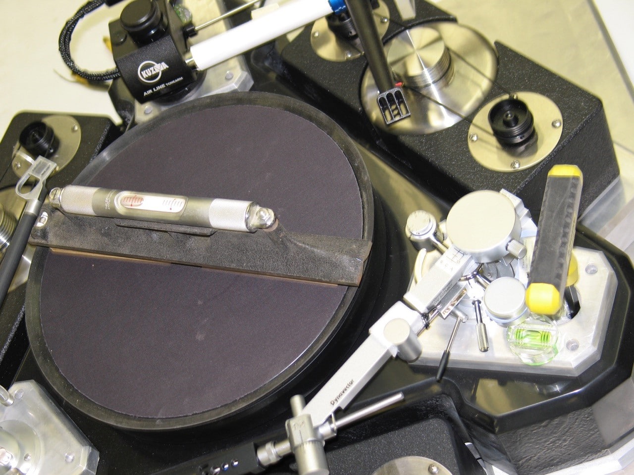
 Here we see the platter with a 12” Starret machinist level atop. On the right side, you will notice a T-handle allen wrench going through the plinth down to the brass adjustment point that is used to level the table. The Starret machinist level has graduations equal to 1/1000th of an inch per foot.
  Pictured are the aluminum pieces I designed to hold the inverted bearing for the Sota vacuum platter I will be using.
  Here we see the anodized bearing cup supports installed on the fiberglass plinth.
 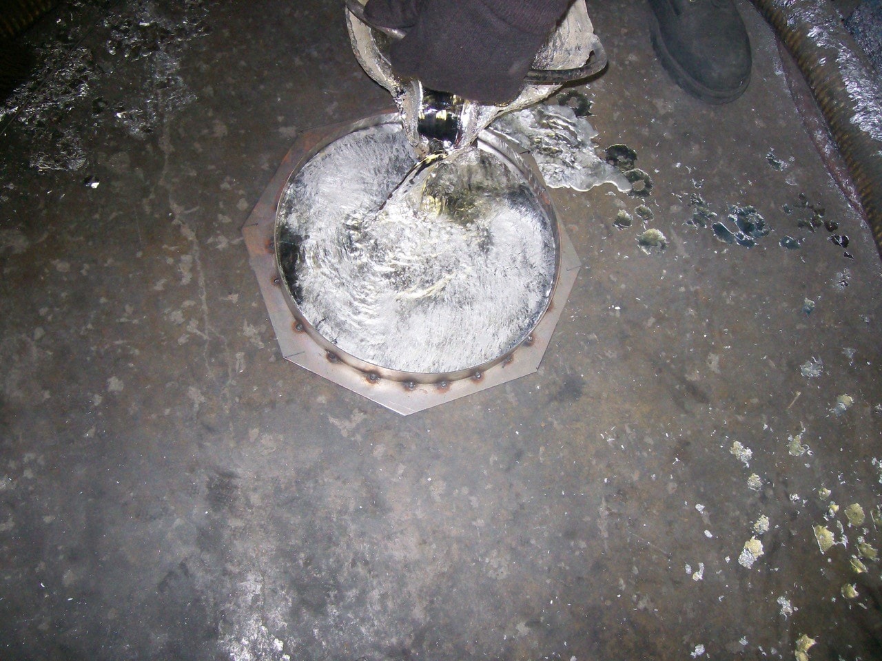 A steel mold was fabricated for casting the 1” thick lead disc that will be bonded to the top of a standard Sota vacuum platter. This steel mold was sent to a supplier in Ohio that casts lead parts for the medical industry. Two of these platters were poured, rather than just one, in case I thought some day I might make a second turntable. Yeah right.
 Here we have a good friend of mine, an expert machinist, finishing out the lead discs.
  A closeup view of the machining operation. After the two lead discs are machined, they were sent to Sota Industries so that they could bond this plate to the top of the Sota sub-platter. After that process was completed, the acrylic/rubber vacuum disc was then bonded to the top of the lead disc.
Depicted here is one of the two completed platters that came back from Sota. They bonded and finished the edges of the platter in the same manner they finished their standard Sota platters. This lead disc added approximately 85 pounds to the weight of the existing Sota vacuum platter. Before I decided to implement an extra lead disc, I conferred with Kirk and Donna at Sota regarding the weight capacity of the ball in their inverted bearing system. They told me that David Fletcher, who was instrumental in the design and weight capacity of their inverted bearing system, designed it for a weight capacity of 150 pounds. After the platter was installed, a dial indicator was used to measure the runout of the lead platter. It was immeasurable, as was the runout on the Sota platter to which it was bonded.
[We will continue with Part 3 in the next issue—Ed.]
0 comments