In the last two installments of this series, I discussed measurements of the two components most prone to developing or causing problems, namely our ears, and room acoustics. The rest of the components in an audio system are perhaps less problematic, but no less worthy of attention.
There is little point in measuring commercial electronic equipment (amplifiers, preamplifiers, digital players and so on) unless you are a reviewer or if you are one of those people who believe that commercial hi-fi equipment is always suboptimal, and it is always possible to squeeze additional performance out of it (i.e. doing “mods”). Some people have a firm belief that only boutique internal components (like capacitors and resistors) could ever sound good, and proceed to rip out all the standard parts and replace them with boutique parts that are ten or even a hundred-fold more expensive. However, while it is true that manufacturers have to take into consideration the cost of production (except for a handful of products targeting multi-millionaires), the specific internal components in a product are often chosen by the designers to achieve a particular sonic result. Changing to something more expensive might change the characteristics of the sound, but is it necessarily for the better? The designers might have tried dozens of alternatives to arrive at their final choice. Would audiophiles do the same, or do they rely on hearsay to decide what to install?
That said, upgrading transistors and op-amps might actually yield some benefits, as the performance of these components has been improving all the time. Op-amps tend to have a bad reputation amongst audiophiles, who might be horrified to learn that the microphone preamps, recorders, mixing desks, compressors, limiters and other professional audio equipment that were used to record their cherished LPs and digital music were most likely chock full of them. Modern op-amps are far quieter, have lower distortion and higher slew rates than the best examples from 20 years ago. However, before you go and swap them all for AD797s (one of the highest-performance audio op-amps currently available), beware that the op-amp could end up oscillating, and modifications to the feedback network might be needed to make sure that does not happen.
Another worthwhile endeavor is to ensure that the transistors are matched in differential circuits and in output stages that utilize parallel devices. An advanced semiconductor analyzer such as the PEAK Atlas DCA75 Pro costs less than $100. Transistors are inexpensive items; buy a whole bunch of them and match them up in pairs and quads. Matching the DC current gain (hFE) is important in differential circuits. The DCA75 Pro measures the hFE at a constant collector current. Beware, however, that the measurement is temperature-sensitive, and holding the transistor between your fingers while doing the test could change the measurement. Also, match both the hFE and the VBE (base-emitter voltage) for parallel output devices, otherwise one device will always conduct more than the other, shortening its life. A friend recently decided to revamp his Bryston power amplifier, and after removing all the output transistors, he found out that they were very poorly matched. Whether they became mismatched over time or started life this way is unknown.
![]()
As for passive components, most high-quality thin film resistors have performance characteristics that are very close to perfect at audio frequencies. In situations such as phono stages, it would be worth using high-performance resistors such as bulk metal foil precision resistors. These are much more stable and have tighter tolerances, lower noise and faster rise times than thin film resistors, but they are much more expensive.
There are other places where using more expensive resistors make sense. Wirewound resistors have significant inductance unless you use non-inductive designs, and the inductance increases with resistance. However, several years ago, I started to notice that some Mills non-inductive wirewound resistors, a brand I had relied on for many years, were becoming noisy. I read that more recently-manufactured Mills (since the company’s takeover by Vishay in 2011) have the resistive wire element clamped to the end caps instead of being bonded to them, and these connections could become noisy with repeated heating and cooling. I also noticed that the resistors are no longer manufactured in the US, which usually means an attempt in cost-cutting.
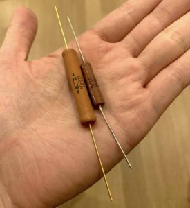
I experimented with military-grade Caddock precision power film resistors (one of the few brands still made in the US.) as tube anode loads and they are excellent. They feel substantial, have gold-plated leads and look indestructible. They look even more high-end than high-end audio components; nothing but the best for Uncle Sam. They are non-inductive, non-magnetic and extremely stable at high temperatures. I had to convince a military supplier to sell them to me, and luckily, they didn’t suspect anything nefarious such as building a nuclear weapon in my garage. There are boutique resistors marketed for audio use that cost more, such as those made with tantalum film, but I have no experience with them and the explanations for their supposed superiority do not sound convincing to me. Other audio resistors that use ancient technologies, such as carbon film and carbon composition, are only useful for restoring antique equipment in order to preserve their character, or to add “tone” to guitar amplifiers.
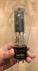
Personally, I tend to be very conservative when specifying the power handling capabilities of resistors, and I usually over specify by a factor of 4 to 5 fold. For example, I would use a 0.5-watt resistor if the steady-state power dissipation is 100mW. This is an important consideration when restoring antique equipment. You certainly don’t want to save 30 cents on a resistor if a short can take out your 300B output tube or damage your output transformer.
The original Quad II amplifier has a 180ohm resistor that is prone to failure. The resistor connects the cathode winding of the output transformer primary to ground (which means it determines the cathode voltage of the amplifier’s two KT66 output tubes), and a shorted resistor would result in a huge increase in the current going through the transformer winding. It is the reason why many examples of this amplifier on the market have tar leaking out of the output transformers; they’ve been damaged by excessive current. The original schematic indicates that the resistor has a voltage drop of 26 volts across it, which any high school student with a calculator can work out dissipates 3.75W. Yet, the actual resistor installed in the amp is rated at 3W. Peter Walker was known to be rather frugal, but it is really inexcusable to save a few pennies on something so crucial. If you are lucky enough to buy a pair of Quad II amplifiers with undamaged output transformers, I would advise changing these resistors to new ones rated at 7W or above before you do anything else.
My Mark Levinson No. 27.5 power amplifier is 27 years old, and after changing all the power supply caps four years ago, it is as good as new. Everything in there was massively over-specified, and it cost a fortune when new, but in retrospect it was actually very reasonably priced after considering how it has lasted several times longer than its less-well-made competitors. I can sell it today and the proceeds will still buy me a very decent new power amplifier.
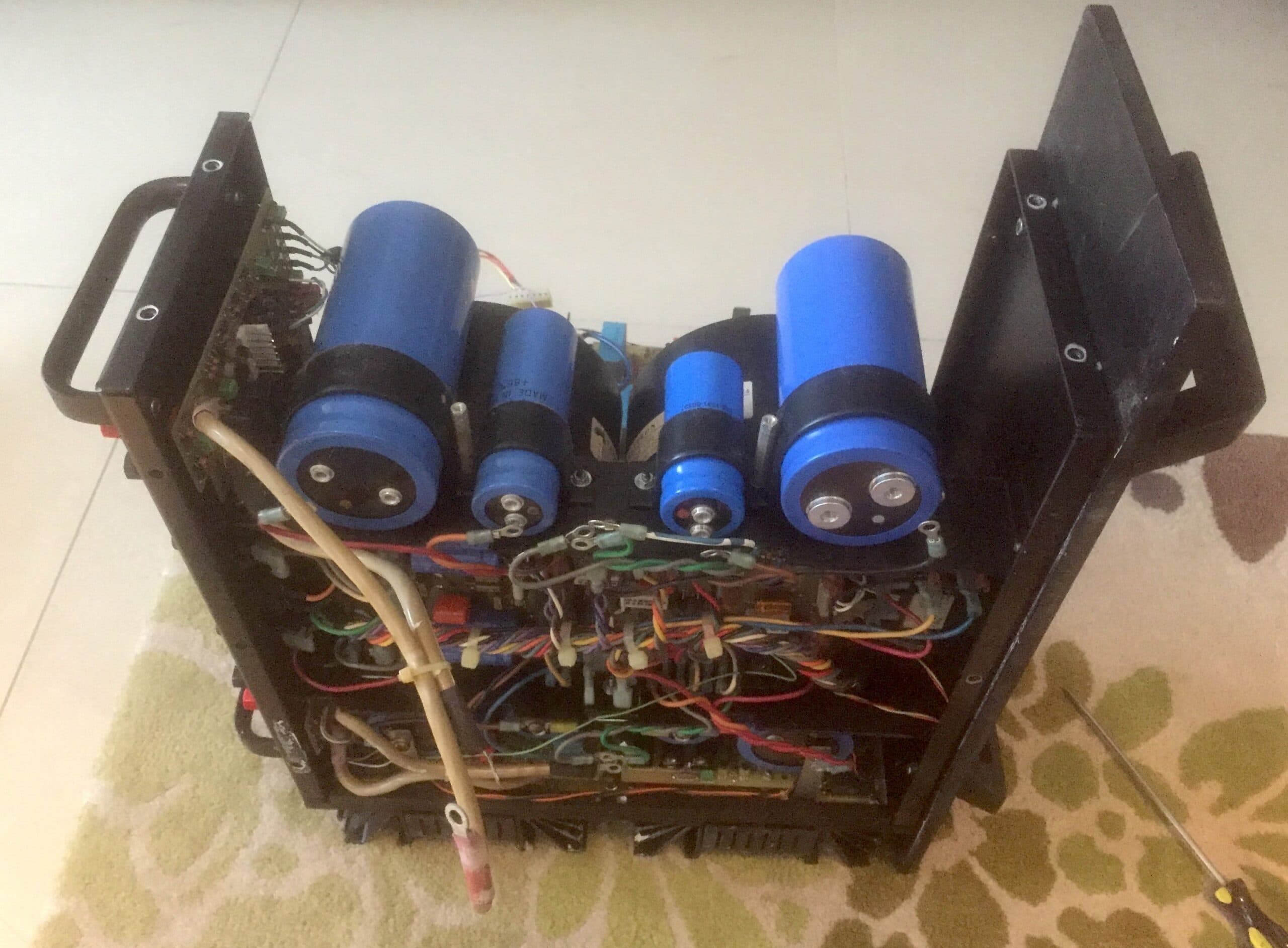 Replacing the power supply capacitors of my Mark Levinson No. 27.5 power amplifier. It took me a while to find the appropriate GE capacitors, one of the few that are still made in the US.
Boutique audio capacitors are all the rage amongst many if not most audiophiles. Several enthusiasts have published, on their blogs, listening tests on hundreds of different brands and models. The problem with these listening tests, however, aside from the fact that the testers were not blinded to the identity of the components under test and cost has a large placebo effect (in other words, they didn’t do blind or double-blind tests), was that none of them measured the technical performance of the capacitors. These measurements matter a great deal, as parameters such as dissipation factor, equivalent series resistance (ESR), parasitic inductance, leakage current and dielectric absorption (DA) determine how much a capacitor will alter the signal. The type of film, the quality of the material and the construction all play a role in defining a capacitor’s electrical characteristics.
Teflon has the best dielectric properties (lowest dielectric constant, highest dielectric strength), closely followed by polystyrene, polypropylene and polyethylene. Polyphenylene-sulfide (PPS) has become popular within DIY audio circles in recent years, and I use them in my preamplifier. They have very low ESR and DA, and are very stable at high temperatures. However, they are hard to find and the range of available values and voltage ratings is limited. Most PPS capacitors are of the surface-mount type (due to their resistance to heat during flow soldering), which makes them a pain to work with for DIYers.
Film and metal foil capacitors have better ability to handle large current surges and lower series resistance than metallized film capacitors, and should be used in high-current situations such as passive loudspeaker crossovers. However, they are larger in size, more expensive and, unlike metallized film caps, they are not self-healing (this is the ability of a capacitor to withstand a momentary short or dielectric breakdown under voltage). Teflon film capacitors do have performance advantages in high-temperature environments such as tube amps, but their cost-benefit ratio is steep.
Many audiophiles think of boutique audio capacitors as artisanal products made by dedicated craftsmen in their garages. The truth is, many of these products are made by OEM manufacturers (original equipment manufacturers) that also make industrial capacitors, since only these companies have the economy of scale and the technical expertise required to manufacture to the tight tolerances expected of modern components.
There are products that use different metal foils in their construction, such as tin, aluminum, copper, zinc, silver and even gold. I have not seen any actual scientific evidence that explains why one metal should be better than the other, but there’s the placebo effect at play: having spent a three-figure sum for a capacitor made of precious metal, how can it sound any other way than magical? Some audiophile capacitors use oil-impregnated plastic or paper. Paper-in-oil capacitors were originally developed for higher-power applications for safety reasons, since the oil helps cool the capacitor, prevents arcing between the plates and because these types of capacitors are self-healing. Paper-in oil-capacitors were commonly used in antique tube amplifiers for the same reasons, since these amplifiers operated at high voltages, and partly accounted for their “antique sound.”
The dielectric absorption of a capacitor is the residual voltage remaining after the capacitor has been fully discharged. This residual voltage introduces distortion to the signal, and a low DA is a prerequisite for a high-performance audio capacitor. The DA of a polypropylene film capacitor is around 0.02 percent, and adding oil impregnation will increase the figure to around 2 percent. Guitar players like to use paper-in-oil capacitors to alter the tone of their amplifiers. Why audiophiles want to use them in the signal path of a modern amplifier is a mystery to me, unless their aim is to introduce some distortion into their music.
So, how does one choose which capacitor to use? After all, every manufacturer claims their products to be superior. Some capacitors do have their own particular sonic character, shaped by the imperfections of their performance (assuming a perfect capacitor would impart no alteration to the signal). This then becomes an art form like cooking, where one tries to achieve a certain taste by using different herbs and spices. But if the goal in an audio component is to minimize alteration to the signal, one should choose the highest-performance capacitors based on the measured parameters listed above.
Over the years, my friends and I have tested dozens of boutique capacitors, and we have arrived at the conclusion that price is an unreliable predictor of performance. In fact, one of the most expensive capacitors on the market, claimed to be handmade, had such poor measured performance that installing it would be akin to adding Jalapeno chili to a dish. But even if some of these boutique capacitors have measured well, I have found them frustrating. Used in high-voltage, high-temperature environments, such as for coupling in tube power amplifiers, reliability often became an issue. I have lost count how many times I’ve had to change capacitors due to an increase in noise (having horn loudspeakers with a sensitivity of 110 dB doesn’t help). And thanks to one of these boutique capacitors, I now have a defunct 300B tube that I keep as a daily reminder of my folly. Nowadays, I just stick to good old Wima film and foil capacitors; they are reliable workhorses and are delightfully free of sonic character.
It is worthwhile investing in an LCR meter, which measures inductance, capacitance and resistance, and an ESR meter, which measures equivalent series resistance. The ESR of electrolytic caps rises as a result of aging, which can start to affect the sound of audio equipment well before the capacitance drifts out of range. The electrolytic caps in the power supply of your amplifiers are often rated at 2,000 to 5,000 hours, and the life is shortened by high operating temperature (e.g. Class A operation, or poorly-ventilated equipment placement) and high ripple current. A friend of mine once proudly told me that he leaves his system powered on during the day so that it does not need to “warm up” if he decides to listen in the evening. He was horrified to learn that the caps would only last a year under these circumstances. For normal people who use their systems on average an hour each day, the caps would need replacing every 5 to 12 years. The amp will not break down suddenly, but the rise in the ESR will cause the output resistance of the power supply to increase, potentially causing dynamic compression during loud passages. A final cautionary note: if you decide to check on the capacitors yourself, make sure they have been adequately discharged, as they can store enough charge to electrocute someone.
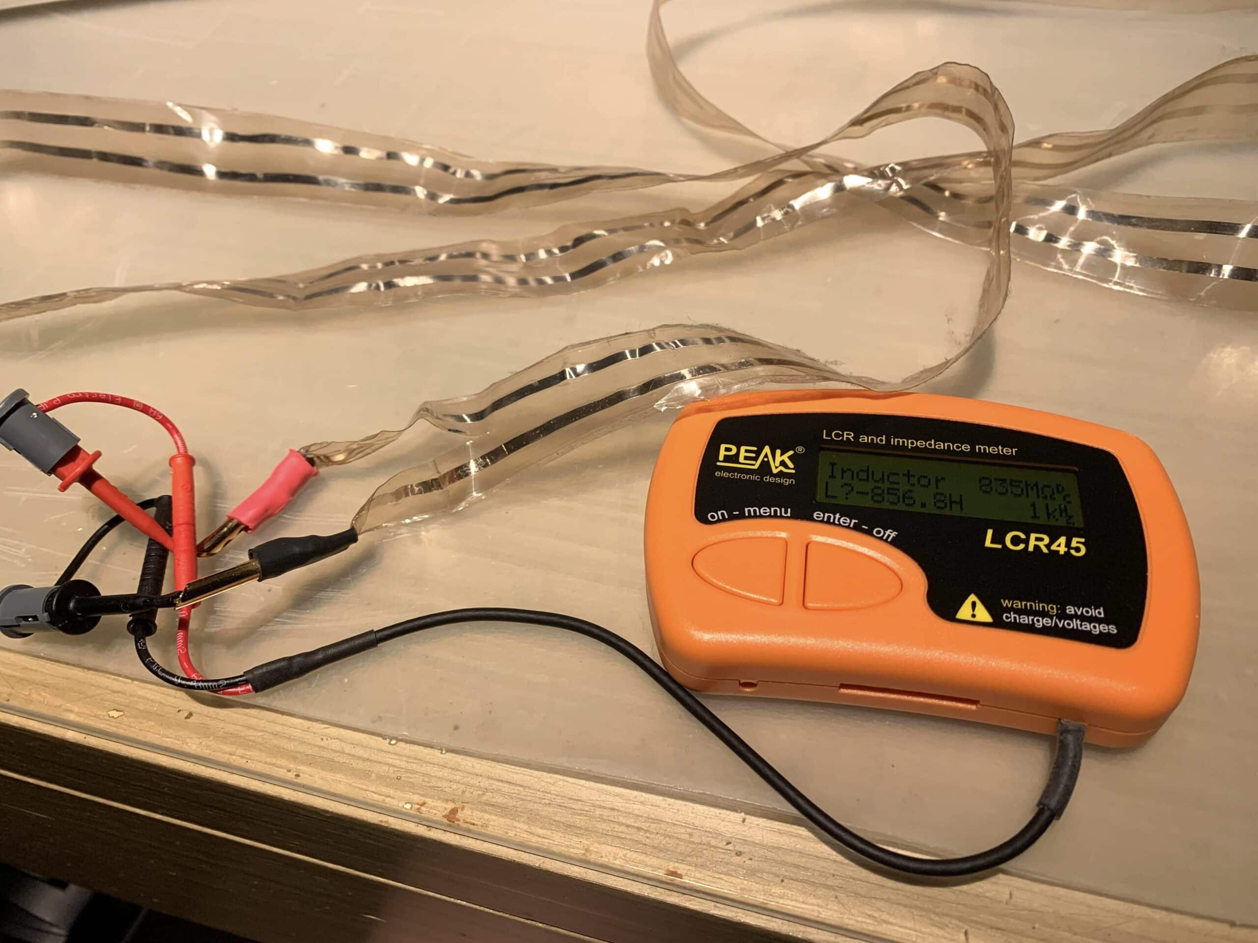
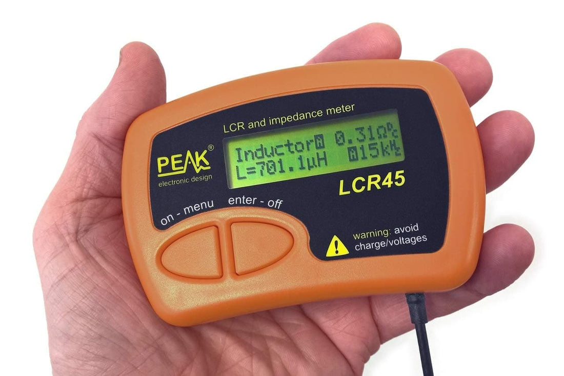
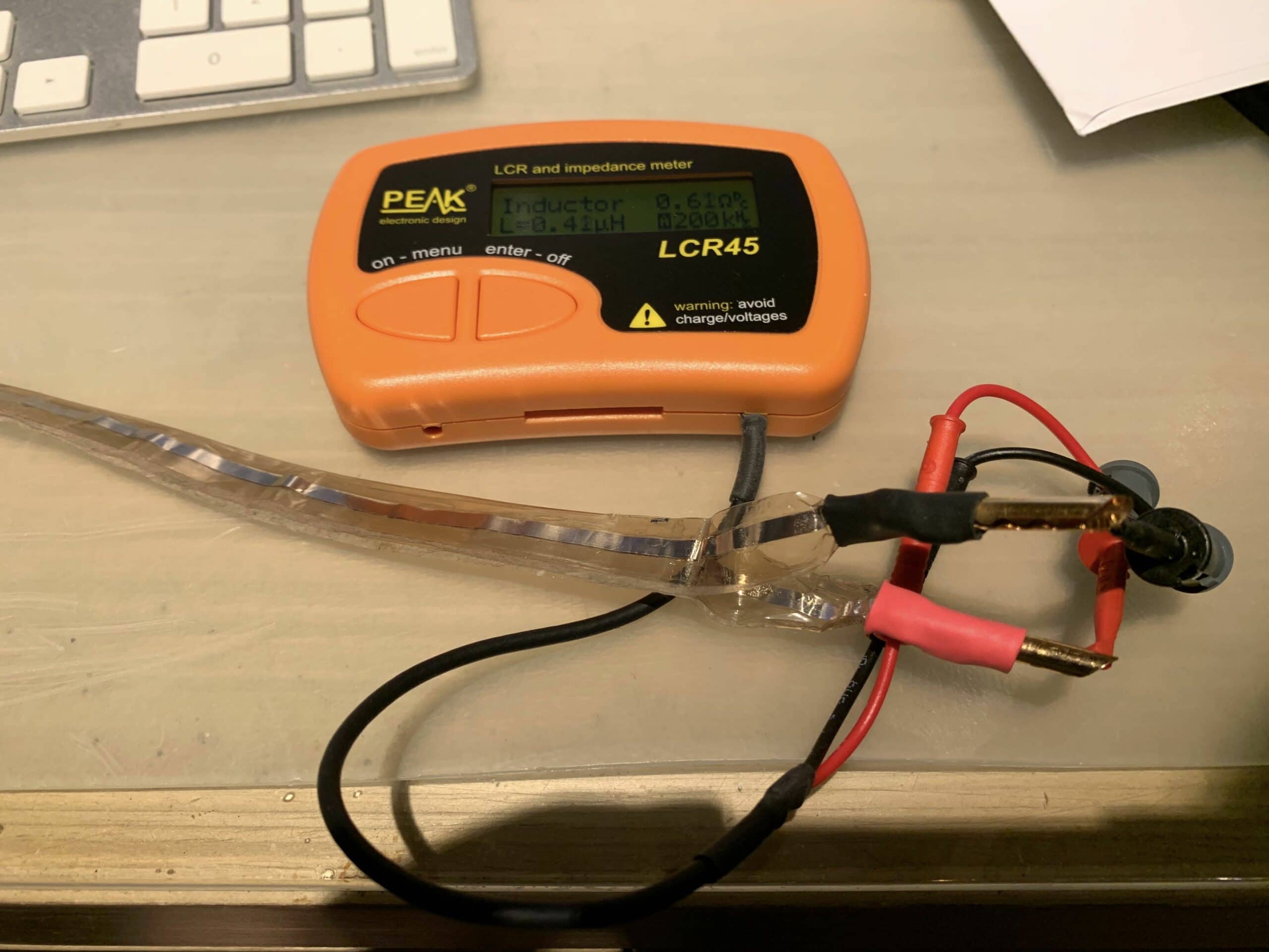 Using the Peak LCR45 meter to measure the impedance of my DIY speaker cable. After reading Max Townshend's article in Issue 124, I measured the characteristic impedance of my DIY silver foil speaker cables. With the conductors side by side, the impedance was 340 ohms. Placing the foils on top of each other reduced the impedance to 30 ohms, which should work well enough for my 16-ohm drivers. Readers with long runs of interconnects should also check the capacitance of the cables to make sure there is no significant high-frequency rolloff. The rolloff frequency is equal to 1/(2 x pi x output impedance x cable capacitance). The output impedance of the equipment should be listed in the owner's manual. I would advise allowing a rolloff frequency of no lower than 100 kHz to minimize change in the phase spectrum.